Operator's IVlanuai CRnFTSMRH ° PROFESSIONAL CHIP-N-VAC DO NOT RETURN Model No. 486.24717 For Missing Parts or Assembly Questions Call 1-866-576-8388 CAUTION: ,, ,, ,, ,, ,, Before using this product, read this manual and follow all Safety Rules and Operating Instructions. Sears, Roebuck and Co., Hoffman TO STORE Safety Assembly Operation Maintenance Parts Estates, IL 60179 U.S.A. www.sears.com/craftsman PRINTED IN U.S.A. FORM NO.
WARRANTY ................................................................ 2 SAFETY RULES .......................................................... 3 FULL SIZE HARDWARE CHART ................................ 6 CARTON CONTENTS ................................................. 7 ASSEMBLY .................................................................. 8 OPERATION .............................................................. 16 MAINTENANCE ........................................................
Any power equipment can cause injury if operated improperly or if the user does not understand how to operate the equipment. Exercise caution at all times, when using power equipment. • Read and follow all instructions in this manual before attempting to assemble or operate this equipment. Failure to comply with these instructions may result in personal injury. Keep this manual in a safe place for future reference and for ordering replacement parts.
TO AVOID SERIOUS iNJURY • • • • • • • • • • • • • Read Owner's Manual and all safety labels on machine before starting and using machine. Do Not remove top cover or attempt to empty contents of cart while engine is running. Do Not stand behind cart in exhaust discharge area while engine is running. Keep hands, feet, face, long hair and clothing out of chipper inlet, vac inlet, and discharge area. There are ROTATING BLADES inside these openings. Wear approved safety glasses and gloves.
These accessories were available when the unit was purchased. They are also available at most Sears retail outlets and service centers. Most Sears stores can order repair parts for you when you provide the model numbers of your tractor and Chipper Vac System. \ \ / \ \ The Hand Wand Attachment, Model 486.24509 provides a 12' x 5" diameter hose to clean around shrubs, patios, window wells and other areas not accessible to the tractor.
SHOWN FULL SIZE A / -J B / C / D E I---:--:---_ F G H i ..... J _.._ j 0 -.............. _ / N ........ \ K \ / p S Q R r.................................................................................. _=.<_j U NOT SHOWN FULL SIZE CC DD / W J X y Z AA / See page 14 for the Deck Adapter REF. A B C D E F G H I J K L M N O P 6 QTY. CART VAC 3 --1 2 --4 -2 -6 -14 9 20 -4 12 -= 6 2 36 = 3 = 1 4 = 9 40 / hardware package.
1 _9 10 CARTON CONTENTS (Cart Body Carton) REF. 1 2 3 4 5 QTY. 1 1 1 1 2 DESCRIPTION Wheel Support Rear Tongue Front Tongue Hose Hanger Rod Cart Body 1 REF. 6 7 8 9 10 QTY, 1 1 1 1 2 DESCRIPTION Hose Tailgate Reinforcement Bracket Axle Latch Stand Bracket Wheels 5 3 \ \ m _ /_ s 7 6 11 \ \ \ \, 12 13 \ CARTON CONTENTS (Mow-N-Vac Carton) RER 1 2 3 4 5 6 7 QT_ 1 2 1 1 2 1 1 DESCRIPTION Front Panel Side Panels Rear Door Cross Brace Hose Clamp Adapter Bracket Deck Adapter Cal11-866-576-8
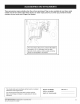
This unit is shipped WITHOUT GASOLINE or OIL. After assembly, see separate engine manual for proper fuel and engine oil recommendations. TOOLS (1) (!) (2) (2) (2) REQUIRED FOR ASSEMBLY Screwdriver Pliers 7/16" Wrenches 1/2" Wrench 9/16" Wrenches • (2) 3/4" Wrenches (only if figure 23 on page 12 is used) REMOVAL • OF PARTS FROM CARTONS Fit the tailgate reinforcement bracket over the end of the cart bed.
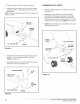
Assemble the wheel support to the bottom of the cart using eight 5/16" x 3/4" truss head bolts and 5/16" nylock nuts as shown in figure 4. Heads of bolts go on the inside of cart. Tighten. * Position the rear tongue on the wheel support and the latch stand bracket. Assemble the axle through the wheel support and the tongue. See figure 6. iMPORTANT: Make sure the tongue is securely locked to the latch stand bracket by the latch lock lever.
• Flipthecartoversothatit restsonitswheels. Assemble the front tongue on top of the rear tongue using three 3/8" x 3" hex bolts and 3/8" nylock nuts. See figure 8. HINT: For easier assembly, support the rear tongue with a block of wood. ASSEMBLING VAC PARTS • 3/8" x 3" HEX BOLT % Release the latch lock lever and tilt the cart bed back. See figure 10. Assemble the front panel to the cart bed, sliding the bottom lip of the panel in between the cart bed and the latch stand bracket.
Place a side panel on top of the cart bed flange, inside the lip of the front panel. Fasten the side panel to the front panel using three 1/4" x 5/8" hex bolts and 1/4" nylock nuts. Fasten the side panel to the cart bed flange using two 1/4"x 5/8" hex bolts, 1/4" flat washers and 1/4" nylock nuts. Tighten. See figure 11. Repeat on other side. Assemble a door latch at each end of the cross brace using a 5/16" x 3/4" hex bolt, a nylon washer and a 5/16" nylock nut.
• Assemble a shorttarpstrapto reardoorusingone 1/4"x 1-1/4"hexbolt,two1/4"flatwashersandone 1/4"nylocknut.Assemblean"S"hookthroughloose endofstrap.Seefigure15.Repeatonothersideof door. Assemble doortorearofcartbyrestingbottomof doorondoorsupportsandpushingtopofdoorin againstcrossbrace.Securetopofdoorusingdoor latchesoneachside.Seefigure15. Hookboththetarpstrapsontothe1/4"x 1"hexbolts inthesidesofthecart.Seefigure15.
Assemble the hose adapter (nozzle) to the front of the impeller housing and secure with the three knobs. Make sure that the switch actuator bracket contacts the switch on the housing. See figure 18. HOSE ADAPTER (NOZZLE) KNOB HINT: Tip the cart bed back for easier access in the next paragraph. *. Attach the chipper chute assembly to the weld bolts on the back side of the impeller housing using three 5/16" flat washers and 5/16" Nylock nuts. Tighten. See figure 20.
BEFORE PROCEEDING, look in the fold-out sheets included with this manual to find templates for Sears mower decks, if written instructions are printed on the template, follow those instructions instead of the instructions in this manual. ASSEMBLING THE DECK ADAPTER TOTHE MOWER DECK (#62468) Remove the mower discharge deflector from your mower deck. Save the deflector and hardware for remounting deflector.
Position the adapter over the deck opening, and check for fit of cutout as shown in figure 24. Trim cutout, if necessary, to allow tilting of adapter, keeping the fit as close as possible for best vacuum suction. NOTE: Make sure adapter clears gauge wheels on mower deck • Assemble the adapter bracket to the deck using two 5/16" x 1-1/4" hex bolts, 5/16" flat washers and 5/16" nylock nuts. See figure 26.
BEFORE • • • HOW TO USE YOUR CHIP-N=VAC STARTING Your Chip-N-Vac engine is shipped without oil or gasoline. Service the Chip-N-Vac engine with oil and gas as instructed in the separate engine manual. Inspect the Chip-N-Vac to make sure all covers (rear door, vinyl boot, elbow, hose adapter, hose and deck adapter are properly attached. Check tires for proper inflation (12 - 14 Ibs). WARNING: Never fill fuel tank indoors, or with the engine running, or while the engine is hot.
USING THE CHIPPER • CHUTE Material such as stalks or heavy branches up to 3" in diameter may be fed into the chipper chute as shown in figure 29. Be sure to wear eye protection and gloves when feeding material into the chipper chute. Use the tamper plug, not your hands, to force material down through the chipper chute. For best performance, it is important to keep the chipper blades sharp. If the composition of the material being discharged changes (becomes stringy, etc.
CUSTOMER • RESPONSiBiLiTiES Read and follow the maintenance schedule and the maintenance procedures listed in this section. MAINTENANCE SCHEDULE Fill in dates as you complete regular service. Service Dates Check for loose fasteners X Check soft vinyl boot X Check tire pressure X Check engine oil level X Lubricate X Clean X X Maintain engine per instructions below and in engine manual.
SHARPENING BLADES OR REPLACING CHIPPER NYLOCK NUTS c-_ • Disconnect the spark plug wire and move wire away from the spark plug. Remove the access plate by removing two hex lock nuts. See figure 30. Locate one of the chipper blades in the access plate opening by rotating the impeller assembly by hand. Remove the blade using a 3/16" allen wrench on the outside of the blade and a 1/2" wrench on the impeller assembly', inside the housing. Remove the other blade in the same manner. ................ c......
PROBLEM POSSIBLE CAUSE(S) CORRECTIVE ACTION Engine fails to start 1. 2. 3. 4. . Connect wire to spark plug. 2. Correctly install hose adapter nozzle. 3. Fill tank with clean, fresh fuel. 4. Open fuel shut-off valve. Spark plug wire disconnected. Safety switch not contacted. Fuel tank empty, or stale fuel. Fuel shut-off valve closed (if so equipped). 5. Faulty spark plug. Loss of power; operation erratic. 1. Spark plug wire loose 2. Unit running on CHOKE. 3. Blocked fuel line or stale fuel. .
NOTES Cal11-866-576-8388formissingpartsorassemblyhelp DO NOT RETURN TO STORE 21
NOTES 22 Cal11-866-576-8388formissingpartsorassemblyhelp DO NOT RETURNTO STORE
REPAIR PARTS FOR MODEL 486.24717 CART BODY 12 J 11 2 / 11 13 11 / 1 4 / / 6 \ 8 \ \ \ 27. 20 \ 22 18 \ \ \\ \\\ 14 lg 17 16 24 REE 1 2 3 4 5 6 7 8 9 10 11 12 13 14 PART NO. QT_ 23985 2 62458 1 23507Y 1 24497Y 1 24897 1 46272 2 43093 2 43601 4 44678 2 43014 2 43866 9 47189 9 43814 12 41076 2 DESCRIPTION Cart Body Tailgate Reinforcement Wheel Support Latch Stand Bracket Bracket Axle, Wheel 1" Dia. Wheel w/Tire, 15 x 6.00 Cotter Pin, 1/8" Dia.
REPAIR PARTS FOR MODEL 486.24717 25 PROFESSIONAL CHIP-N-VAC 26 27 52,53,54,55 23 24 35 38 35 12 15.__ \ 4 _ 28 39 40 22 8 ® \ \ 13 20 21 40 8 \\ 14 13 c_ 16 -@ 5O 9 I I e_ 13 ' 13 34 / 18 ADAPTER 31 2 19 #62468 30 51 12 36 24 Call 1-866-576-8388 for missing parts or assembly help DO NOT RETURN TO STORE
REPAIR PARTS FOR MODEL 486.24717 REF. PART NO. QTY. 1 2 3 4 5 6 24080 24078 24958 43182 43840 43085 1 2 1 14 2 4 7 8 9 10 11 12 13 14 15 16 17 731-1617 47810 43791 47630 712-0421 43012 47189 40995 40998 681-0068 49974 46420 1 24 1 4 3 23 48 1 1 1 1 1 18 19 20 21 22 43792 43793 24678 24679 23836 23 64244 DESCRiPTiON PROFESSIONAL CHIP=N=VAC REF. PART NO. QTY.
REPAIR PARTS FOR MODEL 486.24717 iMPELLER HOUSING PROFESSIONAL ASSEMBLY CHIP=N=VAC @ REF. 1 2 3 4 5 6 7 8 9 10 11 12 13 14 26 PART NO. 629-0241A 63993 24633 43182 710-0772 710-1268 43063 712-0421 47810 43086 719-0330B 725-1700 725-3166 726-0272 QTY. DESCRIPTION 1 Harness, Wire REF. 15 1 1 12 4 2 3 3 Housing Ass'y. inner Housing Ass'y.
SUGGESTED GUIDE FOR SIGHTING OF TRACTOR WITH ATTACHMENT SLOPES FOR SAFE OPERATION FOLD ALONG LINE SLc ONLY RIDE UP AND DOWN NOT ACROSS HILL 10 DEGREES & HILL, MAX. WARNING: To avoid serious injury, operate your tractor up and down the face of slopes, never across the face. Do not operate on slopes greater than 10 degrees. Make turns gradually to prevent tipping or loss of control. Exercise extreme caution when changing direction on slopes. Braking may be affected by tractor attachment.
Your Home For expert troubleshooting and home solutions advice: www.managemyhome.com For repair - in your home - of all major brand appliances, lawn and garden equipment, or heating and cooling systems, no matter who made it, no matter who sold it! For the replacement parts, accessories and owner's manuals that you need to do-it-yourself. For Sears professional installation of home appliances and items like garage door openers and water heaters.