
Instruction Manual


ENGLISH
10
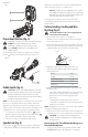
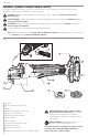
Mounting Sanding Backing Pads
(Fig.A,E)
NOTE: Use of a guard with sanding discs that use backing
pads, often called fiber resin discs, is not required. Since a
guard is not required for these accessories, the guard may or
may not fit correctly ifused.
WARNING: Failure to properly seat the clamp nut
and/or pad could result in serious injury (or damage to
the tool orwheel).
WARNING: Proper guard must be reinstalled for
grinding wheel, sanding flap disc, wire brush or
wire wheel applications after sanding applications
arecomplete.
1. Place or appropriately thread backing pad
16
on
thespindle.
2. Place the sanding disc
17
on the backingpad.
3. While depressing spindle lock button
4
, thread the
sanding clamp nut
18
on spindle, piloting the raised
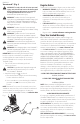
Fig.D
6
15
5
3
Fig. C
Over 1/8" (3.17mm)
wheels
Backing Flange
Locking flange
1/8" Or less (3.17mm)
wheels
Backing Flange
Locking flange
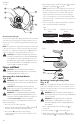
Removing Guard (Fig. B)
To remove the guard, open the guard latch, rotate the guard
so that the lugs on the guard are aligned with the slots on
the gear case cover, and pull the guard away from the gear
casecover.
NOTE: The guard is pre-adjusted to the diameter of the gear
case hub at the factory. If, after a period of time, the guard
becomes loose, tighten the adjusting screw 14 with latch
in the closed position and guard installed on thetool.
CAUTION: Do not tighten the adjusting screw with
the latch in the open position. Undetectable damage
to the guard or the mounting hub may result. If the
guard cannot be tightened by the guard latch, do not
use the tool and take the tool and guard to a service
center to repair or replace theguard.
Fig.B
14
9
13
13
21
22
4. While depressing the spindle lock button
4
, thread the
threaded locking flange
6
onspindle.
NOTE: If the wheel you are installing is more than 1/8"
(3.17mm) thick, place the threaded clamp nut on the
spindle so that the raised section (pilot) fits into the
center of the wheel. If the wheel you are installing is
1/8" (3.17mm) thick or less, place the threaded clamp
nut on the spindle so that the raised section (pilot) is not
against thewheel.
5. To remove the wheel, depress the spindle lock button
and loosen the threaded lockingflange.
Flanges and Wheels
CAUTION: Turn unit off and remove the battery
pack before making any adjustments or removing/
installing attachments or accessories. .
Mounting Non-Hubbed Wheels
(Fig. C, D)
WARNING: Failure to properly seat the flanges and/or
wheel could result in serious injury (or damage to the
tool orwheel).
CAUTION: Included flanges must be used with
depressed center Type 27/42 grinding wheels. See the
Accessories Chart for moreinformation.
WARNING: Use of a damaged flange or guard or
failure to use proper flange and guard can re sult in
injury due to wheel breakage and wheel contact. See
the Accessories Chart for moreinformation.
Depressed center Type 27 grinding wheels must be used
with included flanges.
1. Place the tool on a table, guardup.
2. Install the unthreaded backing flange
5
on spindle
3
with the raised center (pilot) facing the wheel.
3. Place wheel
15
against the backing flange,
centering the wheel on the raised center (pilot) of the
backingflange.