
Operating Guide


5
ENGLISH
ASSEMBLY AND ADJUSTMENTS
WARNING: To reduce the risk of
serious personal injury, turn unit off and
disconnect it from power source before making
any adjustments or removing/installing
attachments or accessories. An accidental start-up
can causeinjury.
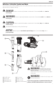
Blower Tube Assembly (Fig. A, C, D, E)
1. Rotate the fan cover
9
counterclockwise. Close and
latch fan cover
9
as shown in the inset of Figure C.
Rotate the center of the fan cover clockwise to close the
interlock switch.
NOTE: Unit will not operate in blow mode without fan
cover closed and the center of the fan cover must be
rotated clockwise to close the interlock switch.
NOTE: Align the upper and lower tubes as shown in
Fig.C.
2. Push the lower blower tube
4
firmly into the upper
blower tube
3
, until the tubes click intoplace.
NOTE: Blow tubes must be assembled to the power
head beforeuse.
NOTE: Never operate without both lower and upper
tubesassembled.
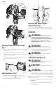
3. In the interest of safety, it is not intended for the blower
tubes to be separated onceassembled.
4. Push the blower tube assembly onto the power head
2
until it is in the fully locked position (Fig.D).
5. Use the air concentrator attachment
5
to target air flow
to a tighter area. Add the attachment to the assembly as
shown in Fig. E. Push on until hole in tab engages raised
post ontube.
Vacuum Tube Assembly (Fig. F, G, H)
NOTICE: Ensure the vacuum is switched
off and disconnected from the power supply before
attaching or removing the vacuum tube. The vacuum
tube and collection bag must be assembled to the
housing before use. The vacuum tubes must be
assembled together beforeuse.
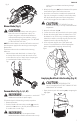
CAUTION: CUT HAZARD. Ensure the tube
assembly is securely seated and latched intoposition.
1. Vacuum tubes must be assembled together beforeuse.
2. Align the notches and the triangles on upper
6
and
lower vac tubes
7
. (Fig. F)
3. Push the lower tube firmly into the upper tube, until the
triangles click into place. (Never operateapart).
NOTE: In the interest of safety, it is not intended for the
tubes to be separated onceassembled.
4. Rotate the center of the fan cover
9
counterclockwise.
Unlatch the latch
18
and open the fan cover
9
.
5. Attach the vacuum tube assembly to the power head
(Fig. H) by locating the assembly as indicated by arrow,
then align the four tube lock tabs on the tube with the
four locking slots. Insert the tube into the housing and
twist clockwise to lock the tube into place and close the
interlock switch.
Fig.E
5
Fig.F
6 7
Fig. C
2
3 4
Fig.D
2
9