
Instruction Manual


5
ENGLISH
Cutting Capacity
The wide vise opening and high pivot point provide cutting
capacity for many large pieces. Use the cutting capacity
chart to determine total maximum size of cuts that can be
made with a newwheel.
CAUTION: Certain large, circular or irregularly shaped
objects may require additional holding means if they
cannot be held securely invise.
CAUTION: Do not cut magnesium or wood with
thistool.
Intended Use
Your chop saw has been designed for the cutting of
variously shaped steelmaterials. It is designed only for
use with reinforced bonded abrasives. Diamond or TCT or
toothed blades should not be used with thisunit.
DO NOT use under wet conditions or in presence of
flammable liquids orgases.
Your chop saw is a professional power tool.
DO NOT let children come into contact with the tool.
Supervision is required when inexperienced operators use
thistool.
SPECIFICATIONS
CMEM2500
Voltage 120V~
Frequency 50/60 Hz
Power input 15 amp
No-load speed 3800/min (rpm)
Wheel diameter 14" (355 mm)
Wheel thickness 0.1" (3 mm)
Net weight 34.1 lbs (15.5 kg)
Bore diameter 1" (25.4 mm)
ASSEMBLY AND ADJUSTMENTS
WARNING: To reduce the risk of serious personal
injury, turn unit off and disconnect it from
power source before making any adjustments or
removing/installing attachments or accessories.
An accidental start-up can causeinjury.
Motor
Be sure your power supply agrees with the nameplate
marking. Voltage decrease of more than 10% will cause loss
of power and overheating. These tools are factory tested; if
this tool does not operate, check power supply.
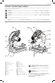
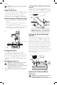
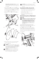
Lifting and Transporting the Chop Saw
(Fig. A)
Fold down unit to position where you can carry the saw.
Push in lock pin
1
to lock armdown. Lift and carry using
the lift and carry handle
18
.
Unlocking (Fig. A)
To unlock tool and raise head, depress motor arm slightly
and pull lock pin
1
out. Motor arm will then pivotupward.
Mounting (Fig. A)
CAUTION: Tool must be supported on stable, level,
non-skid surface to prevent unexpected movement
whenoperating.
1. Drill holes through the work surface that align the base
of the chopsaw.
2. Insert four M10 screws down through the mounting
holes
17
in the base and through holes in mounting
surface. The approximate length of the screws should be
the thickness of the mounting surface plus 4" (102mm).
Spark Deflector Adjustment (Fig. A)
To best deflect sparks away from surrounding persons and
materials, loosen the spark deflector screw
2
, adjust the
spark deflector
3
and then retighten screw. Do not allow
cordset to come into contact with deflector or sparks as
damage to cordset mayoccur.
Depth Stop (Fig. A)
Depth stop is set at the factory for a new 14" (355 mm)
wheel to prevent wheel from cutting into the supporting
surface. To allow more depth of cut, use a wrench (not
provided) to loosen the depth stop bolt and jam nut
14
and raise bolt to desired height and then turn jam nut
clockwise until seated firmly on the casting. Securely tighten
the depth stop bolt beforeuse.
OPERATION
WARNING: To reduce the risk of serious personal
injury, turn unit off and disconnect it from
power source before making any adjustments or
removing/installing attachments or accessories.
An accidental start-up can causeinjury.
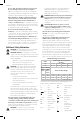
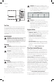
Maximum Cutting Capacity
NOTE: Capacity shown on chart assumes no wheel wear
and optimum fenceposition.
Workpiece
Shape
90° Cutting
angle
A = 4-7/8"
(125 mm)
A = 4-1/2"
(115 mm)
4-1/2" x 5-1/8"
(115 mm x 130 mm)
A = 4-3/4"
(120 mm)
45° Cutting
angle
A = 4-1/2"
(115 mm)
A = 3-13/16"
(98 mm)
3-3/4" x 4-1/8"
(95 mm x 105 mm)
A = 4-1/8"
(105 mm)
SAVE THESE INSTRUCTIONS FOR
FUTURE USE
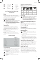
.....................safety alert symbol
.....................visible radiation
..................... avoid staring at
light
..................... wear respiratory
protection
..................... wear eye
protection
..................... wear hearing
protection
..................... read all
documentation
IPXX .................... IP symbol