
Instruction Manual


7
ENGLISH
trigger switch is in the OFF position. Do not make
any adjustment while the wheel is in motion. Do not
make any adjustment while chop saw is plugged into
powersupply.
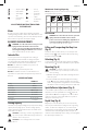
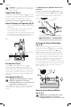
1. Push in spindle lock
12
and rotate wheel
10
by hand
until wheel lock lever engages slot in inside flange
23
to lock wheel. Loosen the bolt
20
counterclockwise in
the center of the abrasive wheel with the 5/16" (8mm)
hex wrench
7
. Bolt has right-handthread.
2. Remove the bolt, washer
21
, outside flange
22
and
old wheel.
Fig.E
12
Fig. F
20
21
22
10
23
3. Make sure flange surfaces are clean and flat. Install the
new abrasive wheel by reversing the abovesteps.
4. Do not overtightenbolt.
WARNING: Check the work surface that the chop saw
rests on when replacing with a new abrasive wheel. It
is possible that the wheel may contact ANY ITEMS OR
STRUCTURE THAT EXTENDS ABOVE work surface
(under the base) when the arm is fullylowered.
WARNING: Always keep the screw attached to the
guard and make sure the center guard in the right
position after replacing wheel and before use, to
protect user from high speed rotating wheel.
CAUTION: Only use 14" (335 mm) Type 1/41 wheels
with 1" (25.4 mm) arbor hole with this tool. Never
force a wheel onto the machine or alter the size of the
arborhole.
Operation Tips for More Accurate Cuts
• Allow the wheel to do the cutting. Excessive force will
cause the wheel to glaze reducing cutting efficiency
and/or to deflect causing inaccuratecuts.
• Properly adjust fenceangle.
• Make sure material is laying flat acrossbase.
• Properly clamp material to avoid movement
andvibration.
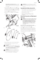
Motor Brush Inspection and Replacement
(Fig. G, H)
WARNING: To reduce the risk of injury, turn unit
off and disconnect machine from power source
before installing and removing accessories,
before adjusting or changing set-ups or when
making repairs. Be sure the trigger switch is
in the OFF position. An accidental start-up can
causeinjury.
BE SURE TOOL IS UNPLUGGED BEFORE INSPECTING
BRUSHES. Brushes should be regularly inspected for wear.
To inspect brushes, remove brush cap
24
.
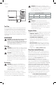
Brushes
25
should slide freely in brush box. If brushes
are worn down to 0.3" (8 mm) as shown in Figure H they
should be replaced. To reinstall, push new brush back
into brush box. If replacing existing brush, maintain same
orientation as when removed. Replace the brush cap (do
notovertighten).
Fig.G
24
25