
Use And Care Manual


ENGLISH
6
CAUTION: When changing to a new wheel, readjust
depth stop to original position to prevent cutting into
supportingsurface.
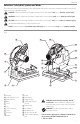
Trigger Switch (Fig. A)
To start the tool, depress the trigger switch
13
. To turn the
tool off, release the trigger switch. Keep hands and material
from wheel until it has coasted to a stop. To prevent
unauthorized use of tool, install a standard padlock (not
included) into the padlock hole
15
located in thetrigger.
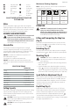
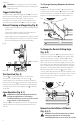
Material Clamping and Supporting (Fig. B)
• Angles are best clamped and cut with both legs resting
againstbase.
• A spacer block slightly narrower than the work piece
can be used to increase wheelutilization.
• Long workpieces must be supported by a block so it will
be level with top of base (Fig. B). The cut off end should
be free to fall downward to avoid wheelbinding.
Block
Cut-off end
Fig.B
Vise Operation (Fig. A)
The vise
6
has a quick-travel feature. To release the
vise when it is clamped tightly, turn the crank
8
counterclockwise one or two times to remove clamping
pressure. Lift vise lever
9
up. Pull crank assembly out as far
as desired. Vise may be pushed forward into work without
cranking. Lower vise lever then tighten vise
6
on work by
usingcrank.
Fence Operation (Fig. A, C)
WARNING: Turn off and unplug the tool before
making any adjustments or removing or
installing attachments or accessories. Be sure the
trigger switch is in the OFFposition.
The fence
5
can be adjusted two ways: to change desired
cutting angle and to change spacing between the fence
andvise.
To Change Spacing Between the Fence
and Vise
Using the 5/16" (8mm) hex wrench
7
provided, loosen
and remove the two fence bolts
16
. Adjust the fence
5
to desired locations. Insert both fence bolts in provided
locations. Securely tighten both fence bolts before use.
Fig.C
16
5
To Change the Desired Cutting Angle
(Fig. A, D)
Use the 5/16" hex wrench
7
provided to loosen (do not
remove) the two fence bolts
16
. Align the desired angle
indicator line with the slot line in the base
4
. Securely
tighten both fence bolts before use. For more accurate
square cuts, disconnect the power supply, loosen the two
fence bolts, push arm down until wheel extends into base.
Place a square against the wheel and adjust fence against
the square. Securely tighten both fence bolts before use.
When making a miter cut, the vise
6
may not clamp
securely, depending on the thickness of the workpiece and
the miter angle. Other aids (such as spring, bar or C-clamps)
will be necessary to secure the work piece to the fence
when making thesecuts.
Fig.D
16
Removal and Installation of Wheels
(Fig. A, E, F)
WARNING: Turn off and unplug the tool before
making any adjustments or removing or
installing attachments or accessories. Be sure the