
Instruction Manual


ENGLISH
4
ASSEMBLY AND ADJUSTMENTS
WARNING: To reduce the risk of serious personal
injury, turn unit off and disconnect it from
power source before making any adjustments or
removing/installing attachments or accessories.
An accidental start-up can causeinjury.
WARNING: Laceration Hazard. Before attempting any
of the following operations, make sure that the tool is
switched off and unplugged and that the saw blade
has stopped. Used saw blades can be hot.
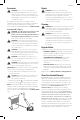
Blade Installation (Fig. B)
1. Push the saw blade locking lever
3
upward.
2. With teeth facing forward, insert the shank of the saw
blade into the blade holder as far as it will go.
3. Release the lever.
4. Check to ensure blade is secure before cutting.
Fig.B
3
Adjusting the Shoe for Bevel Cuts
(Fig. A, C, D)
WARNING: Never use the tool when the shoe is loose
or removed.
The shoe can be set to a left or right bevel angle up to 45°.
1. Turn saw upside down. Use a screwdriver to loosen the
clamping screw
9
and clamp plate
10
.
2. Slide the shoe
5
forward and rotate left or right to the
required angle.
The label on your tool may include the following symbols. The
symbols and their definitions are asfollows:
V ......................... volts
Hz .......................hertz
min ..................... minutes
or DC ......direct current
...................... Class I Construction
(grounded)
…/min ..............per minute
BPM .................... beats per minute
IPM ..................... impacts per minute
RPM .................... revolutions per
minute
sfpm ................... surface feet per
minute
SPM .................... strokes per minute
OPM .................... oscillations per
minute
A ......................... amperes
W ........................watts
or AC ...........alternating current
or AC/DC .... alternating or
direct current
...................... Class II
Construction
(double insulated)
n
o
.......................no load speed
n .........................rated speed
......................earthing terminal
.....................safety alert symbol
.....................visible radiation
..................... avoid staring at
light
..................... wear respiratory
protection
..................... wear eye
protection
..................... wear hearing
protection
..................... read all
documentation
../min or ..min
-1
. Revolutions or
Reciprocations per
minute
2
.................. two phase
alternating current
2N
............... two phase
alternating current
with neutral
3
.................. three phase
alternating current
3N
............... three phase
alternating current
with neutral
x
.................. rated current of the
appropriate fuse-
link in amperes
A
............ time-log miniature
fuse-link where X
is the symbol for
the time/current
characteristic, as
given in
IEC 60127-3
IPXX .................... IP symbol
Motor
Be sure your power supply agrees with the nameplate
marking. Voltage decrease of more than 10% will cause loss
of power and overheating. These tools are factory tested; if
this tool does not operate, check power supply.
Intended Use
This jig saw is designed for household applications.
DO NOT use under wet conditions or in presence of
flammable liquids orgases.
DO NOT let children come into contact with the tool.
Supervision is required when inexperienced operators use
thistool.
Minimum Gauge for Cord Sets
Volts
Total Length of Cord in Feet
(meters)
120 V 25 (7.6) 50 (15.2) 100 (30.5) 150 (45.7)
240 V 50 (15.2) 100 (30.5) 200 (61.0) 300 (91.4)
Ampere Rating
American Wire Gauge
More
Than
Not
More
Than
0 6 18 16 16 14
6 10 18 16 14 12
10 12 16 16 14 12
12 16 14 12 Not Recommended
Components
Tool Use
jig saw household
SAVE THESE INSTRUCTIONS FOR
FUTURE USE