USER MANUAL WARNING: To reduce the risk of injury, user must read instructions before using product. SERVICE PARTS DIRECT ALL INQUIRIES TO CRAFTSMAN CUSTOMER SERVICE AT 888-331-4569. Outside the United States call your local distributor. Please provide the Model Number when calling. LOCATING MODEL # INFORMATION Model numbers and other information required for service parts is located on a label on the interior right side. CAPACITIES • The maximum weight for each shelf should be no more than 50 lbs.
SAFETY WARRANTY DANGER is used to indicate a hazardous situation which, if not avoided, will result in serious injury or death. Garage Storage CRAFTSMAN TEN YEAR LIMITED WARRANTY WARNING indicates a hazardous situation which, if not avoided, could result in serious injury or death. FOR TEN YEARS from the date of purchase, this product is warranted against any defects in material or workmanship. With proof of purchase, a defective part will be replaced free of charge.
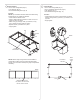
HARDWARE CARTON CONTENTS TOOLS REQUIRED: Socket wrench 3/8” socket 7/16” deep-well socket 7/16” open end wrench Square Screwdriver, Flathead Screwdriver, Crosstip Drill 1/8” drill bit 1/4” drill bit Stud finder A. Side Panel B. Top C. Back Panel D. Shelf E. Door Left F. Door Right G. Bottom H.
Items Needed: 1/4-20 x 5/8" Carriage Bolt (Qty: 4) 1/4-20 x 3/4" Button Head Screw (Qty: 8) 11/32" Washer (Qty: 4) 1/4-20 Serrated Flange Nut (Qty: 12) Side panel Process: • Insert top into one end of assembly and attach using (4) bolts, (8) screws, (4) washers, and (12) nuts. • Finger tighten. Nut Back panel Screw Top Items Needed: 1/4-20 x 3/4" Button Head Screw (Qty: 3) 1/4-20 Serrated Flange Nut (Qty: 3) Process: • Connect assemblies from step 1 using (3) 1/4-20 x 3/4” screws and (3) nuts.
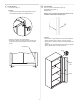
Items Needed: 1/4-20 x 5/8" Carriage Bolt (Qty: 4) 1/4-20 x 3/4" Button Head Screw (Qty: 8) 11/32" Washer (Qty: 4) 1/4-20 Serrated Flange Nut (Qty: 12) Items Needed: 1/4-20 x 5/8” Carriage Bolt (Qty: 6) 11/32” Washer (Qty: 6) 1/4-20 Serrated Flange Nut (Qty: 6) Process: NOTE: Top and bottom shelves should have slots facing toward back of unit. Install top shelf first. • Insert shelf from bottom of unit. • Place in desired mounting location in back of unit, and rotate into place as shown.
Items Needed: Leveling Foot (Qty: 4) Items Needed: #8 - 32 x 3/8" Pan Head Screw (Qty: 16) Single Bitted Lock (Qty: 1) Magnet (Qty: 1) Process: • Install (4) leveling feet. Some adjustments may be necessary after cabinet is in desired location. NOTE: Lock on the 48-inch wide floor cabinet is not installed. Install before attaching door. Process: • Ensure lock on right side door is in the unlock position. • Attach right side door as shown, using (8) screws.
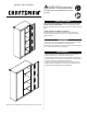
Items Needed: Grommet (Qty: 2) • Align cabinet with a stud. Adjust leveler feet if needed. • Drill 1/8" pilot hole. • Attach cabinet to stud using 14-10 X 3” Screw. Process: • Place the grommet in the holes at back of cabinet. Screw Items Needed: 1/4-20 x 3/4" Button Head Screw (Qty: 1) 1/4-20 Serrated Flange Nut (Qty: 1) 14-10 X 3" Screw (Qty:1) WARNING Cabinet MUST be attached to a stud in a wood frame wall. Failure to do so may cause personal injury or product damage.
OPERATION Shelf Adjustment • Empty shelf. • Remove fasteners. • Rotate shelf upward and pull forward, as shown. • Move shelf to desired location. • Insert back of shelf in notches, rotate shelf into place and reinstall fasteners. Leveling Foot Adjustment • Adjust leveling foot to desired position with flat head screwdriver or 7/16 open end wrench as shown.
MANUAL DEL USUARIO ADVERTENCIA: Para reducir el riesgo de lesiones, el usuario debe leer todas las instrucciones de seguridad antes de usar el producto. PIEZAS DE RECAMBIO EN LOS ESTADOS UNIDOS, LLAME AL 888-331-4569 PARA PEDIR PIEZAS DE RECAMBIO. Fuera de los Estados Unidos, llame a su distribuidor local. Informe el número de modelo cuando llame.
SEGURIDAD GARANTÍA PELIGRO se utiliza para indicar una situación peligrosa que, de no evitarse, provocará lesiones graves o la muerte. Almacenaje de herramientas GARANTÍA LIMITADA DE 10 AÑOS POR CRAFTSMAN ADVERTENCIA Indica una situación peligrosa que, de no evitarse, podría provocar lesiones graves o la muerte. Este producto está garantizado contra defectos materiales o de fabricación por DIEZ AÑOS a partir de la fecha de compra.
FERRETERÍA CONTENIDO DE LA CAJA HERRAMIENTAS NECESARIAS: Llave de cubo Cubo de 3/8” Cubo profundo de 7/16” Llave de extremo abierto de 7/16” Cuadrado Destornillador, cabeza plana Destornillador, punta en cruz Taladro Broca de taladro de 1/8” Broca de taladro de 1/4” Localizador de vigas A. Panel lateral B. Parte superior C. Panel trasero D. Estante E. Puerta izquierda F. Puerta derecha G. Parte inferior H.
Elementos necesarios: Perno con cabeza de hongo de 1/4-20 x 5/8” (Cant.: 4) Tornillo de cabeza ciega de 1/4-20 x 3/4” (Cant: 8) Arandela de 11/32” (Cant: 4) Tuerca con brida dentada de 1/4-20 (Cant.: 12) Panel lateral Proceso: • Inserte la parte superior en un extremo del ensamble y sujete con (4) pernos, (8) tornillos, (4) arandelas y (12) tuercas. • Ajuste a mano.
Elementos necesarios: Perno con cabeza de hongo de 1/4-20 x 5/8” (Cant.: 4) Tornillo de cabeza ciega de 1/4-20 x 3/4” (Cant: 8) Arandela de 11/32” (Cant: 4) Tuerca con brida dentada de 1/4-20 (Cant.: 12) Elementos necesarios: Perno con cabeza de hongo de 1/4-20 x 5/8” (Cant.: 6) Arandela de 11/32” (Cant: 6) Tuerca con brida dentada de 1/4-20 (Cant.: 6) Proceso: NOTA: Los anaqueles superior e inferior deben tener ranuras orientadas hacia la parte posterior de la unidad. Instale el anaquel superior primero.
Elementos necesarios: Pata niveladora (Cant.: 4) Elementos necesarios: Tornillo de cabeza plana #8 - 32 x 3/8” (Cant.: 16) Cerradura de un solo lado (Cant.: 1) Imán (Cant.: 1) Proceso: • Instale (4) patas niveladoras. Se pueden necesitar algunos ajustes una vez que el gabinete está en el lugar deseado. NOTA: La cerradura en el gabinete para piso de 48 pulgadas (121.92 cm) de ancho no está instalada. Instale antes de colocar la puerta.
Elementos necesarios: Sombrerete (Cant.: 2) • Alinee el gabinete con una viga. Ajuste las patas de nivelación de ser necesario. • Perfore un orificio piloto de 1/8”. • Sujete el gabinete a la viga con un tornillo de 14-10 X 3”. Proceso: • Coloque el sombrerete en el orificio en la parte trasera del gabinete. Tornillo Elementos necesarios: Tornillo de cabeza ciega de 1/4-20 x 3/4” (Cant: 1) Tuerca con brida dentada de 1/4-20 (Cant.: 1) Tornillo de 14-10 X 3” (Cant.
FUNCIONAMIENTO Ajuste Estante • Ajuste de los anaqueles • Vacíe la balda. • Quite los seguros. • Gire la balda hacia arriba y tire hacia delante tal y como se muestra. • Cambie la balda a la posición deseada. • Inserte la parte posterior de la balda en las ranuras, gire la balda hasta colocarla en su lugar y vuelva a colocar los seguros.
MANUEL D’UTILISATION AVERTISSEMENT : Afin de réduire le risque de blessure, l’utilisateur doit lire toutes les instructions de sécurité avant d’utiliser le produit. PIÈCES D’ENTRETIEN AUX ÉTATS-UNIS, CONTACTEZ LE 1-800-262-2161 POUR LES PIÈCES DE RECHANGE. En dehors des États-Unis, appelez votre distributeur local. Veuillez fournir le numéro de modèle lors de l’appel.
SÉCURITÉ GARANTIE Rangement d’outil GARANTIE LIMITÉE DE 10 ANS DE CRAFTSMAN DANGER est utilisé pour indiquer une situation dangereuse qui, si elle n’est pas évitée, entraînera des blessures graves ou la mort. Ce produit est garanti contre tout défaut de matériel ou de main-d’œuvre PENDANT 10 ans à partir de la date d’achat. Sur présentation d’une preuve d’achat, une pièce défectueuse peut être remplacée gratuitement.
MATÉRIEL CONTENU DE L’EMBALLAGE OUTILS REQUIS : Clé à douille Douille de 9.5 mm (3/8 po) Douille longue de 11.1 mm (7/16 po) Clé à fourche de 11.1 mm (7/16 po) Équerre Tournevis, tête plate Tournevis, tête cruciforme Perceuse Mèche de 3.2 mm (1/8 po) Mèche de 6.35 mm (1/4 po) Détecteur de montant A. Panneau latéral B. Haut C. Panneau arrière D. Tablette E. Porte gauche F. Porte droite G. Bas H. Plaque de fixation B A (2) C (2) MATÉRIEL INCLUS : Boulon de carrosserie de 15.
Éléments nécessaires : Boulon de carrosserie de 15.88 mm (1/4 -20 x 5/8) (Qté : 4) Vis à tête ronde 19.05 mm (1/4 - -20 x 3/4) (Qté : 8) Rondelle de 8.73 mm (11/32 po) (Qté : 4) Écrous à embase cannelée (1/4 - 20) (Qté : 12) Panneau latéral Processus : • Insérer la surface supérieure à un des bouts de l’assemblage et l’immobiliser au moyen de quatre (4) boulons, huit (8) vis, quatre (4) rondelles et douze (12) écrous. • Serrer avec les doigts.
Éléments nécessaires : Boulon de carrosserie de 15.88 mm (1/4 -20 x 5/8) (Qté : 4) Vis à tête ronde 19.05 mm (1/4 - -20 x 3/4) (Qté : 8) 11/32" Washer (Qty: 4) Écrous à embase cannelée (1/4 - 20) (Qté : 12) Éléments nécessaires : Boulon de carrosserie de 15.88 mm (1/4 -20 x 5/8) (Qté : 6) 11/32” Washer (Qty: 6) Écrous à embase cannelée (1/4 - 20) (Qté : 6) Processus : REMARQUE : Les rainures sur les tablettes doivent faire face vers l’arrière de l’armoire. Installer d’abord la tablette du haut.
Éléments nécessaires : Pattes de nivellement (Qté : 4) Éléments nécessaires : Vis à tête cylindrique nº 8, 9.5 mm (32 x 3/8 po) (Qté : 16) Verrou à un profil (Qté : 1) Aimant (Qté : 1) Processus : • Installer quatre (4) pattes de nivellement. Il peut être nécessaire de changer le nivellement une fois que l’armoire est à l’emplacement souhaité. REMARQUE : Pour l’armoire de 122 cm (48 po), la serrure n’est pas installée. Installer la serrure avant de poser la porte.
Éléments nécessaires : Œillet (Qté : 2) • Aligner l’armoire sur l’emplacement du montant. Ajuster les pattes de nivellement au besoin. • Percer un avant-trou de 3.2 mm (1/8 po). • Fixer l’armoire au montant au moyen de la vis de 76.2 mm (3 po). Processus : • Placer l’œillet dans le trou à l’arrière de l’armoire. Vis Éléments nécessaires : Vis à tête ronde 19.05 mm (1/4 - -20 x 3/4) (Qté : 1) Écrous à embase cannelée (1/4 - 20) (Qté : 1) Vis de 76.
FONCTIONNEMENT Réglage de la tablette • Vider la tablette. • Retirer les attaches. • Pivoter la tablette vers le haut et tirer vers l’avant, comme dans l’illustration. • Déplacer la tablette à l’endroit désiré. • Insérez l’arrière de la tablette dans les encoches, la pivoter en place et remettre les attaches. Ajustement de patte de nivellement • Ajuster la patte de nivellement en utilisant un tournevis à tête plate et une clé à fourche de 11.1 mm (7/16 po) comme illustré.