TABLE OF CONTENT Safe Operation Practices .Page Assembly . ...Page Operation Page 19 Service Page 26 PRODUCT SPECIFICATIONS Engine Oil: 5-30 Fuel: Unleaded Gasoline Spark Plug: FLATCAR (Part #951-10292) Spark Plug Gap: 020" t0 0.030" Off-Season Storage. Page 34 Troubleshooting . Page Warranty See Separate Supplement Page 37 MODEL NUMBER Mabel Number Serial Number Date of Purchase Record the model number, serial number, and date of purchase above.
This symbol paints out important safety instructions which, if not followed, could endanger the personal safety and/or property of yourself and others. Read and follow all instructions in this manual before attempting to operate this machine. Failure to comply with these instructions may result in personal injury. When you see this symbol, HEED ITS WARNING! A DANGER This machine was built to be operated according to the safe operation practice sin this manual.
SAFETY INSTRUCTIONS If gasoline is spilled, wipe it off the engine and equipment. Mace unit to another area. Wait 5 minutes before starting the engine. If fuel is spilled on clothing, change clothing immediately. To reduce fire hazards, keep machine free of grass, leaves, or other debris build-up. Clean up vil of fue! spillage and remove any fuel soaked debris.
Observe proper disposal laws and regulations for gas, oil, etc. to protect the environment. . Prior to storing, run machine a few minutes to clear snow from machine and prevent freeze up of auger/impeller. . Never store the machine or fuel container inside where there is an open flame, spark or pilot light such as a water heater, fum ace, clothes dryer etc. . Always refer to the operator’s manual for proper instructions on off-season storage. .
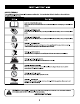
SAFETY INSTRUCTIONS SAFETY SYMBOLS This page depicts and describes safety symbols that may appear on this predict. Read, understand, and follow all instructions on the machine before attempting to assemble and operate. B3l Descriptor READ THE OPERATOR'S MANUAL(S) Read, understand, and follow all instructions in the manual(s} before attempting to assemble and operate. ‘g WARNING— ROTATING BLADES Keep hands out of inlet and discharge openings while machine is running. There are rotating blades inside.
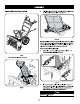
ASSEMBLY NOTE: This Operator's Manual covers several models. Features may vary by model. Not all features in this manual are applicable to all models and the model depicted may differ from yours. Refer to Figure 1 which shows the different versions and match the contents of carton (chute and directional control rod) to identify your specific unit.
LA A NOTE: References to right or left side of the snow blower are determined from behind the unit in the operating position (standing directly behind the snow blower, facing the handle panel). UNPACKING: Removing From Carton 1. Cornerstone the carton and lay the sides flat on the ground. Remove and discard all packing inserts. 2. Move the snow blower out of the carton. 3. Make certain the carton has been completely emptied before discarding it.
ASSEMBLE 4. Place shift lever in Forward-6 position or fastest forward speed (if equipped). 5. Pullman back on upper handier as shown in Figure 5. As you are raising the handle upward, make sure that both ends of the center cable are positioned properly in the brackets, Align upper handle with the lower handle. NOTE: On select units with steel rod speed selectors, you may need to lower shift rod to the side slightly to maneuver handle panel over it when pivoting handle upward, Figure s 6.
ASSEMBLE Standard Side Crank Chute Control I 1 Figure § Position chi rte assembly over base. See Figure 9. Ve Figure 2. Close flange keepers to secure chute assembly to chute base. Flange keepers will click into place when properly secure. See Figure 10. Figure 10 NOTE: Ensure the lower chute is secured to the flange on the chute base. The lower edge of the chute keeper should be positioned below the flange on the chute base after being clicked into place.
ASSEMBLY Overhead Chute Control (w/ Chute Control Rod) J Figure 12 1. Remove wing nut and hex screw from chute control head and clevis pin and cotter pin from chute support bracket. Position chute assembly {forward facing) over chute base. See Figure 13. Chute Control Head Chute Base Figure 13 n 2 Place chute assembly onto chute base and secure chute control head to chute support bracket with clevis pin and cotter pin removed in Step 1.
ASSEMBLY 4. Insert chute control rod into the support bracket on rear of the dash panel. 2.way & 4-Way Chute Control See Figure 16. e . Figure 16 5. Remove hairpin clip (a} from rear of chute control head. See Figure 17, ~ Figure 18 1. Remove hairpin clip, wing nut and hex screw from chute control head and clevis pin and bow-tel cotter pin from chute support bracket. See Figure 19. Auger 17 6. Insert chute control rod (b} into rear of chute control head, See Figure 17.
ASSEMBLE NOTE: For smoothest operation, cables should all be tithe left of the chute 4. Squeeze trigger on joystick and rotate chute hy hand to face forward. The directional control rod. hole sin chute control input will be facing up. See Figure 22. 2. Insert chute control rod into chute control head.
ASSEMBLY 8 Electric Chute Control Figure 24 NOTE: Chute control rod will fit snug into pinion gear. Support rear of dash panel with one hand while inserting rod with your other hand to ensure rod is inserted el the way into pinion gear. NOTE: The hole in the chute directional control rod Is a reference for aligning rod with indicator arrow on pinion gear, and will be visible after rod has been Inserted. Push chute control rod toward control pane! until hole in rod lines up with \ ‘ ) hole in chute control i
a0 2. Insert the round end of the chute control rod into input of chute control 4. Finish securing chute control head by installing hex screw and wing nut head. Push rod as far into the chute control head as possible, keeping the removed in Step 2. See Figure 30. hole sin the rod pointing upward. See Figure 28. Figure 28 3. Place chute onto chute base and ensure chute control rod is positioned under Figure 30 handle panel. Secure chute control head to chute support bracket with clevis 5.
ASSEMBLY 6. Push the chute control rod toward the control panel until the hole in the rod lines up with the middle hole in the chute control input and insert the cotter pin removed in Step 1, See Figure 32. Chute Control Cable Routing (If Equipped) For units equipped with 2-way or 4-way chute control joystick, electric chute control and/or chute-pitch controls, ensure control! cables are routed properly. NOTE: For smoothest operation, cables should all be to the left of the chute directional control rod.
ASSEMBLE Chute Clean-Out Tool Chute clean-out tool is fastened to the top of the auger housing with 2 mounting slip. See Figure 35. The tool is designed to clear a chute assembly of ice and snow. This item is fastened with a cable tie at the factory. Cut the cable tie before operating the snow blower. Never use your hands to clears clogged chute assembly. Shut OFF engine and remain behind handles until all moving parts have stopped before using the clean-out tool to clear the chute assembly.
LA A Auger Control Prior to aerating your snow blower, carefully read and follow all instructions below. Perform all adjustments to verify your snow blower is operating safely and properly. Check the adjustment of the auger control as follows: 1. The auger control is located on the left handle. See Figure 37 inset, When the auger control is released and in the disengaged “UP” position, the cable should have very little slack. It should NOT be tight. 2.
OPERATION Auger Control Lever Shift Lever \ equipped Drive Control Lever Shift Lever LED Light Bar t Chute Assembly Shift Standard 3 Lever Chute a Directional Control Auger Housing R R2 Overhead Shift Lever Electric Chute Chute Directional Directional Control Manual Chute L) Control Chute Directional 3 Joystick Directional Control t Control Joystick Fuel Cap Muffler s Fuel Cap Muffler o oil il N Re coll Starter Choke Control Primary Safety Key Throttle Control \ \ ‘ Button Recoil Starter ‘ Handle % " Electr
OPERATION Now that you have set up your snow blower, it's Important to become acquainted with its controls and features. Refer to Figure 38. NOTE: This Operator’s Manual covers several models. Snow blower features may vary by model. Not all features in this manual are applicable to all snow blower models and the snow blower depicted may differ from yours. NOTE: All references to the left or right side of the snow blower are from the operator’s position. Any exceptions will be noted.
OPERATION Auger Control AUGER CONTROL ~ ¥ S The auger control s located on the left handle. Squeeze the control grip against the handle to engage the auger and start snow throwing action. Release to stop.
OPERATION Four-Way Chute Control (Joystick) (If Equipped) Clean-Out Tool CHUTE DIRECTIONAL CONTROL CHUTE TILT DOWN Never use your hands to clear a clogged chute assembly. Shut off engine and remain behind handles until all moving parts have stopped before using the clean-out tool to clear the chute assembly. The chute dean-out tool is conveniently fastened to the rear of the auger housing ‘with amounting slip.
OPERATION Before Starting Engine Read, understand, and follow all instructions and wakings on the machine and in this manual before operating. il The unit was shipped with oil in the engine. Check oil level before each operation to ensure adequate oil in the engine. NOTE: Be sure to check the engine on a level surface with the engine stopped. 1. Remove the oil filler cap/dipstick and wipe the dipstick lean. 2. Insert the cap/dipstick into the oil filler neck, but do NOT screw it in. 3.
OPERATION Electric Starter The electric starter is equipped with a grounded three-wire power plug, and is designed to operate on 120 volt AC household current. It must be used with a properly grounded three-prong receptacle at all mes to avoid the possibility of electric shod. Follow all instructions carefully prior to operating the electric starter. DO NOT use electric starter in the rain. Determine that your home’s wiring is a three-wire grounded system.
OPERATION Replacing Shear Pins NEVER replace the auger shear pins with anything other than OEM Part No. 738-04124A (round head replacement shear pins), 738-05273 (black colored, round head replacement shear pins) or 738-06654 (hex head replacement shear pins). Any damage to the auger gearbox or other
SERVICE AND MAINTENANCE MAINTENANCE SCHEDULE m Follow the maintenance schedule given below. This chart describes service guidelines only. Use the Service Log column to keep track of completed Be fare performing any type of maintenance/service, disengage all controls | maintenance tasks. To locate the nearest Service Center or to schedule service, call and stop the engine. Walt until all macing parts have come to a complete the following toll free stop.
Used ol Is a hazardous waste product. Dispose of used oil properly. Do not discard with household waste. Cheek with your local authorities or Service Center for safe disposal/recycling fatalities. 5. Reinstall the drain plug and washer (if equipped) and tighten it securely. 6. Refill with the recommended oil and check the oil level. See Recommended 0il Usage chart. NOTE: 208cc and 243cc engines use 600 ml (approx. 20 0z, NOTE: 277cc, 357 and 420cc engines use 1100 ml {approx. 37.2 0z).
Electrode L. Wheels At least once a season, remove both wheels, Clean and coat the axles with a multipurpose automotive grease before reinstalling wheels, Chute Directional Control Once a season, lubricate the eye bolt bushing and spiral with 3-in-1 oil. Auger Shaft v At least once a season, remove the shear pins on auger shaft. Spray lubricant inside 02-03in, shaft, and around the spacers and flange bearings found at either end of the shaft.
SERVICE AN MAINTENANCE 2. Reassemble new shave plate, making sure heads of carriage botheration 6. To ensure proper shift cable tension perform the following: inside of housing, Tighten securely. See Figure 47. 2 Starttheengineand place the shift lever In the slowest forward speed, Using the drive control, ensure the unit moves forward, b. Place the shift lever in the slowest reverse speed.
Drive Control Chute Control Rod When the drive control is released and in the disengaged “up” position, the cable To achieve more chute control rod engagement in the input shaft under the handle should have very little slack. It should NOT be tight. Also, if there is excessive slack panel, the chute control rod will have to be adjusted, Refer to Figure 52, in the drive cable o if the unit experiences intermittent drive while using, the cable 1, adjust ths rod, proceed as follows: may need to be adjusted.
SERVICE AN MAINTENANCE Auger Control Figure 54 Refer to the Assembly section for instructions on adjusting the auger control cable. 3. Roll the auger bat off the engine pulley, See Figure 55, Skid Shoes Refer to the Assembly section for instructions on adjusting the skid shoes. Belt Replacement H Auger Belt To remove and replace your snow blower’s auger belt, proceed as follows: 1. Topreventspillage, remove all fuel from tank by running engine unit ft stops, 2.
Loosen and remove the shoulder screw which acts asa bet keeper. Refer to Drive Belt Figure 57. NOTE: Several components must be removed and special tools are required in order to replace the snow blower's drive belt.
SERVICE AN MAINTENANCE 6. Carefully remove the hex nut and washer which secures the hex shaft to 8. Follow the steps above in reverse order to reassemble components. the snow blower frame and lightly tap the shaft's end to dislodge the ball 9, Perform the test previously described i the Drive Control section. bearing from the right side of the frame. See Figure 60.
OFF-SEASON STORAGE If the snow blower will not be used for 30 days or longer, orig the end of the snow season, the equipment needs to be stored properly. Follow storage instructions below to ensure top performance from the snow blower for future use.
TROUBLESHOOTING Disconnect the spark plug wire and ground it against the engine to prevent unintended starting. Before performing any type of maintenance/service, disengage all controls and stop the engine, Wait until all moving parts have come to a complete stop. Always wear safety glasses during operation or while performing any adjustments or repairs.
TROUBLESHOOTING Unit fails to discharge snow 1. Chute assembly clogged. 1. Stop engine immediately and disconnect spark chute assembly and inside of auger housing with clean-ourt tool. 2. Foreign object lodged in auger, 2. Stop engine immediately and disconnect spark plug wire, Remove object from auger with clean-out tonal. 3. Auger cable in need of adjustment, 3. Adjust auger control cable, Refer to Assembly section. 4. Auger belt loose or damaged. 4. Replace auger belt.