INSTRUCTION MANUAL | MANUAL DE INSTRUCTIONES R100 Series LAWN TRACTOR/TRACTOR CORTACÉSPED Model Nos. CMXGRAM1130035 CMXGRAM1130040 CMXGRAM1222292 CMXGRAM7368327 IF YOU HAVE QUESTIONS OR COMMENTS, CONTACT US. SI TIENE DUDAS O COMENTARIOS, CONTÁCTENOS. 1-888-331-4569 CRAFTSMAN® is a registered trademark of Stanley Black & Decker, Inc., used under license. CRAFTSMAN® es una marca registrada de Stanley Black & Decker, Inc., utilizada bajo licencia. © 2018 CRAFTSMAN U.S. & Canada Only CRAFTSMAN.com WWW.
TABLE OF CONTENTS Safe Operation Practices . . . . . . . . . . . . . . . . . . . . . . . . . Page 3 Off-Season Storage. . . . . . . . . . . . . . . . . . . . . . . . . . . . . . Page 31 Assembly. . . . . . . . . . . . . . . . . . . . . . . . . . . . . . . . . . . . . . . . Page 9 Troubleshooting . . . . . . . . . . . . . . . . . . . . . . . . . . . . . . . . Page 32 Operation . . .
SAFETY INSTRUCTIONS WARNING DANGER This symbol points out important safety instructions which, if not followed, could endanger the personal safety and/or property of yourself and others. Read and follow all instructions in this manual before attempting to operate this machine. Failure to comply with these instructions may result in personal injury. When you see this symbol, HEED ITS WARNING! This machine was built to be operated according to the safe operation practices in this manual.
SAFETY INSTRUCTIONS • Check overhead clearances carefully before driving under low hanging tree branches, wires, door openings etc., where the operator may be struck or pulled from the machine, which could result in serious injury. Do Not: • Do not turn on slopes unless necessary; then, turn slowly and gradually downhill, if possible. • Disengage all attachment clutches and depress the brake pedal completely before attempting to start engine.
SAFETY INSTRUCTIONS • Always use extra caution when towing with a machine capable of making tight turns (e.g. “zero-turn” ride-on mower). Make wide turns to avoid jack-knifing. • Travel slowly and allow extra distance to stop. • Do not coast downhill. • Check brake operation frequently as it is subjected to wear during normal operation. Adjust and service as required. • Check the blade(s) and engine mounting bolts at frequent intervals for proper tightness.
SAFETY INSTRUCTIONS NOTICE REGARDING EMISSIONS SPARK ARRESTOR Engines which are certified to comply with California and federal EPA emission regulations for SORE (Small Off Road Equipment) are certified to operate on regular unleaded gasoline, and may include the following emission control systems: Engine Modification (EM), Oxidizing Catalyst (OC), Secondary Air Injection (SAI) and Three Way Catalyst (TWC) if so equipped.
SAFETY INSTRUCTIONS Symbol Description BYSTANDERS Keep bystanders, helpers, children and pets at least 75 feet from the machine while it is in operation. WARNING— SLOPE OPERATION Do not operate this machine on a slope greater than 12 degrees. WARNING— HOT SURFACE Engine parts, especially the muffler, become extremely hot during operation. Allow engine and muffler to cool before touching. DANGER — ROTATING BLADES To reduce the risk of injury, keep hands and feet away.
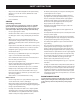
Figure 1 ne shed li 12° da Figure 2 (TOO STEEP) Slopes are a major factor related to tip-over and roll-over accidents which can result in severe injury or death. Do not operate machine on slopes in excess of 12 degrees. All slopes require extra caution. If you cannot back up the slope or if you feel uneasy on it, do not mow it. Always mow up and down the face of slopes, never mow across the face of slopes.
ASSEMBLY Contents of Crate • One Riding Mower • One Seat Assembly • One Discharge Chute Assembly • One Steering Wheel/Shaft Assembly • One Rear Engine Cover • One Hardware Pack • One Rear Hitch Plate • One Oil Drain Sleeve • One Riding Mower Operator’s Manual • One Steering Pedestal Cap Contents of Hardware Pack 4. Before beginning installation, remove all the contents from the crate and all the hardware from the pack to make sure everything is present. Hardware is listed below.
ASSEMBLY Attaching The Seat 5. If the seat for your tractor was not attached at the factory, follow the applicable instructions below to attach it. Position the seat assembly over the seat mounting bracket, aligning the holes provided. 6. Install the two shoulder bolts and lock nuts removed from the seat mounting bracket in Step 1. See Figure 7. 1. Remove the shoulder bolts and lock nuts from the seat mounting bracket included in your hardware pack. See Figure 4.
ASSEMBLY Steering wheel height adjustment 3. To adjust the height of the steering wheel, this unit is equipped with a telescoping steering column. To adjust the height of the steering wheel: 1. Sit in the operator’s seat and place your hands on the steering wheel. 2. Push the button (a) on the steering column and raise or lower the steering wheel (b) to the desired position. See Figure 9. Secure the deck chute by tightening the wing knobs removed earlier. See Figure 10.
ASSEMBLY 2. Install the mulch plug into the deck discharge opening on the deck. The rear of the mulch plug should be under the tab on the rear deck bracket. The studs on the deck surface will fit through the holes on the upper portion of the mulch plug. The small tab on the deck lip area will fit through the square cutout on the lower portion of the mulch plug. See Figure 11. Installing the Hitch Plate 1. Slide the hitch plate in between the frame and the rear cover on your rider. See Figure 14.
ASSEMBLY 3. Remove the plastic cover, if present, from the negative battery terminal and attach the black cable to the negative battery terminal (–) with the remaining hex bolt and hex nut, using a 7/16 inch wrench and socket wrench. See Figure 15. 4. Position the red rubber boot over the positive battery terminal to help protect it from corrosion. NOTE: A 5w30 synthetic oil may be used to improve start ability for cold weather (temperatures below 40 F).
ASSEMBLY Adding Fuel Fuel Requirements CAUTION WARNING Operating the engine with E85 fuel, an oil/gasoline mixture, dirty gasoline, or gasoline over 30 days old without fuel stabilizing additive may result in damage to your engine’s carburetor. Subsequent damage would not be covered under the Craftsman warranty. Use automotive gasoline (unleaded or low leaded to minimize combustion chamber deposits) with a minimum of 87 octane.
OPERATION Clutch/Brake Pedal Speed Control & Parking Brake Lever Fuel Level Indicator Ignition Switch Shift Lever Fuel Fill Cap Throttle/Choke Lever Deck Lift Lever Cup Holder Oil Fill Cap PTO (Blade Engage) Lever Figure 17 NOTE: Any reference in this manual to the RIGHT or LEFT side of the tractor is observed from operator’s seat position facing forward towards the front of tractor.
OPERATION Throttle / Choke Control Shift Lever The throttle control lever is located on the left fender of the tractor as seen from the operator’s position, see Figure 17. This lever controls the speed of the engine, as well as the choke when it is pushed all the way forward. When set in a given position, the throttle will maintain a uniform engine speed. The shift lever is located on the control panel just below the seat, in the center of the tractor.
OPERATION Safety Interlock Switches The safety interlock system is designed for safe operation of the tractor. If this system should ever malfunction, do not operate the tractor. Immediately contact 1-888-331-4569 to have the system serviced. • The safety interlock system prevents the engine from starting unless the parking brake is engaged and the PTO (Blade Engage) lever is in the disengaged (OFF) position.
OPERATION Starting the Engine WARNING Avoid Serious Injury or Death • Know location and function of all controls. • Remove objects which could be thrown by the blades. • Go up and down slopes, not across. • Use extra caution on slopes. Do not mow slopes greater than 12 degrees. Avoid sudden turns. Use low speed. WARNING Do not operate the tractor if the interlock system is malfunctioning. This system was designed for your safety and protection.
OPERATION Driving The Tractor WARNING Avoid sudden starts, excessive speed and sudden stops. WARNING Do not leave the seat of the tractor without first placing the PTO (Blade Engage) lever in the disengaged (OFF) position, depressing the brake pedal and engaging the parking brake. If leaving the tractor unattended, also turn the ignition key off and remove the key. 5. Depress clutch-brake pedal. 6. Place speed control lever in desired position. 7.
OPERATION Engaging the Blades Mowing Engaging the PTO (Blade Engage) transfers power to the cutting deck. To engage the blades, proceed as follows: 1. Move the throttle/choke control lever to the FAST (rabbit) position. 2. Grasp the PTO (Blade Engage) lever and pivot it all the way forward into the engaged (ON) position. 3. Keep the throttle lever in the FAST (rabbit) position for the most efficient use of the cutting deck.
SERVICE AND MAINTENANCE MAINTENANCE SCHEDULE WARNING Before performing any type of maintenance/service, disengage all controls and stop the engine. Wait until all moving parts have come to a complete stop. Disconnect spark plug wire and ground it against the engine to prevent unintended starting. Always wear safety glasses during operation or while performing any adjustments or repairs. Interval Each Use Follow the maintenance schedule given below. This chart describes service guidelines only.
SERVICE AND MAINTENANCE Post-Operation Rider Care 7. 8. After each operation of the rider, the following procedures should be implemented to extend the life of your rider and ensure safe operating conditions. DANGER 9. 10. 11. Failure to follow these recommendations may result in serious injury to yourself or others and may cause damage to the rider. 12.
SERVICE AND MAINTENANCE • Clean the top of the mower deck, under the spindle covers and belt area. See “Figure 3”. Storing the Rider • • Allow the machine to cool in an open area before storing. Do not park the rider near any flammable materials (wood, cloth or chemicals) or any open flames or other potential source of ignition (furnace, water heater or any other type of heater). Remove all combustible materials from the rider before storing. Empty cargo boxes, grass catchers or containers.
SERVICE AND MAINTENANCE 17. Service the Oil Filter if desired, as per the instructions later in this section. 18. Reinstall the drain plug and tighten it securely, 12-14 Nm (106.2-123.9 in-lb). 19. Remove the oil drain sleeve from the oil sump. Return the dipstick to the oil fill tube and screw the oil fill cap back into place. 20. Pour oil into the dipstick tube. Do not over fill. With an oil filter change the high level amount of oil for this engine is 1700 ml (57.48 fl-oz.). 21.
SERVICE AND MAINTENANCE Air Filter Service 2. Remove thumb screw (A). See Figure 8. Paper filters cannot be cleaned and should be replaced every 100 operating hours; more often if used in extremely dusty conditions. WARNING Never use gasoline or low flash point solvents for cleaning the air filter element. A fire or explosion could result. A CAUTION Do not use pressurized air or solvents to clean the air cleaner cartridge.
SERVICE AND MAINTENANCE 6. Attach the new air filter with foam element, aligning the hole in the air filter with the intake manifold. See “Figure 10”. Secure with thumb screw. Spark Plug Service WARNING DO NOT check for spark with spark plug removed. DO NOT crank engine with spark plug removed. To ensure proper engine operation, the spark plug must be properly gapped and free of deposits. 1. Remove the spark plug boot and use a spark plug wrench to remove the plug. See “Figure 12”.
SERVICE AND MAINTENANCE 5. After the spark plug is seated, tighten with a spark plug wrench to compress the washer. The fuel filter cannot be cleaned and should be replaced every 100 operating hours; more often if run with old gasoline. NOTE: When installing a new spark plug, tighten 1/2 turn after the spark plug seats to compress the washer. When reinstalling a used spark plug, tighten 1/8-1/4 turn after the spark plug seats to compress the washer.
SERVICE AND MAINTENANCE 3. Remove the belt from around the tractor’s PTO pulley. See “Figure 15”. WARNING 5. Remove the remaining bow-tie cotter pins securing the deck to the unit, as shown in “Figure 17”. Avoid pinching injuries. Never place your fingers on the idler spring or between the belt and a pulley while removing the belt. Figure 17 NOTE: The bow-tie clips should be re-installed from the top down. Figure 15 4.
SERVICE AND MAINTENANCE 1. 2. 3. 4. 5. It is easiest to change the deck belt by first removing the cutting deck as instructed earlier in this section. Skip this step if deciding to change the deck belt with the mowing deck still installed on the unit. Otherwise, remove the cutting deck now. 8. Tires WARNING If changing the deck belt with the cutting deck still installed on the unit, lower the cutting deck to the lowest cutting position.
SERVICE AND MAINTENANCE Adjustments WARNING Never attempt to make any adjustments while the engine is running, except where specified in the operator’s manual. Leveling the Deck NOTE: Check the tractor’s tire pressure before performing any deck leveling adjustments. Refer to Tires, in this Service And Maintenance section for more information regarding tire pressure. Front To Rear It is possible to adjust the pitch of the cutting deck.
SERVICE AND MAINTENANCE Parking Brake Adjustment 2. WARNING Remove the hex washer screw securing the battery hold-down rod to the frame. See “Figure 24”. Hex Washer Screw Never attempt to adjust the brakes while the engine is running. Always disengage PTO (Blade Engage Lever), move shift lever into neutral position, stop engine and remove key to prevent unintended starting.
SERVICE AND MAINTENANCE Battery Failures Fuse Some common causes for battery failure are: One 15 AMP fuse is installed in your tractor’s wiring harness to protect the tractor’s electrical system from damage caused by excessive amperage. If the electrical system does not function, or your tractor’s engine will not crank; first check to be certain that the fuse has not blown. It can be found under the fender on the left side of the unit, on the wiring harness just above the battery.
OFF-SEASON STORAGE WARNING Never store lawn tractor with fuel in tank indoors or in poorly ventilated areas where fuel fumes may reach an open flame, spark, or pilot light as on a furnace, water heater, clothes dryer, or gas appliance. PREPARING THE ENGINE WARNING Gasoline is a toxic substance. Dispose of gasoline properly. Contact your local authorities for approved disposal methods. IMPORTANT: Fuel left in the fuel tank during warm weather deteriorates and will cause serious starting problems. 3.
TROUBLESHOOTING Problem Engine fails to start Cause 5. PTO/Blade Engage lever engaged. Parking brake not engaged. Spark plug wire(s) disconnected. Throttle/Choke control lever not in correct starting position. Choke not activated 6. 7. 8. 9. 10. 11. Fuel tank empty, or stale fuel. Blocked fuel line. Faulty spark plug(s). Engine flooded. Blown Fuse(s). Safety switch(s) not properly engaged. 1. 2. 3. Unit running with CHOKE activated. Spark plug wire(s) loose. Blocked fuel line or stale fuel. 1. 2. 3.
Notes Page This page intentionally left blank. Use this page to make any notes regarding your tractor.
ÍNDICE Medidas de seguridad. . . . . . . . . . . . . . . . . . . . . . . . . Página 34 Almacenamiento fuera de temporada . . . . . . . . . Página 62 Montaje . . . . . . . . . . . . . . . . . . . . . . . . . . . . . . . . . . . . . . Página 40 Solución de problemas. . . . . . . . . . . . . . . . . . . . . . . . Página 63 Operación . . . . . . . . . . . . . . . . . . . . . . . . . . . . .
INSTRUCCIONES DE SEGURIDAD ADVERTENCIA PELIGRO La presencia de este símbolo indica que se trata de instrucciones importantes de seguridad que se deben respetar para evitar poner en peligro su seguridad personal y/o material y la de otras personas. Lea y siga todas las instrucciones de este manual antes de poner en funcionamiento esta máquina. Si no respeta estas instrucciones podría provocar lesiones personales.
INSTRUCCIONES DE SEGURIDAD • Desenganche la(s) cuchilla(s), coloque el freno de estacionamiento, detenga el motor y espere hasta que la(s) cuchilla(s) se detenga(n) por completo antes de retirar el colector de césped, vaciar los recortes, destapar el canal, retirar restos de césped o desechos, o hacer cualquier ajuste. • Nunca deje la máquina en funcionamiento sin vigilancia. Apague siempre las cuchillas, coloque el freno de mano, detenga el motor y retire la llave antes de bajarse del vehículo.
INSTRUCCIONES DE SEGURIDAD • • Tenga extrema precaución cuando se aproxime a esquinas ciegas, portales, arbustos, árboles u otros objetos que puedan impedirle ver a un niño que se cruce en el recorrido de la máquina. Para evitar accidentes al operar en marcha atrás, siempre desenganche las cuchillas antes de colocar marcha atrás.
INSTRUCCIONES DE SEGURIDAD • Nunca altere el sistema de enclavamiento de seguridad ni otros mecanismos de seguridad. Controle periódicamente que funcionen correctamente. • Después de golpear con algún objeto extraño, detenga el motor, desconecte el cable de la bujía y conecte el motor a masa. Inspeccione minuciosamente la máquina para ver si está dañada. Repare el daño antes de arrancar y utilizar la máquina. • Nunca trate de hacer ajustes o reparaciones a la máquina mientras el motor está en marcha.
INSTRUCCIONES DE SEGURIDAD Symbol Description PELIGRO— DÉ EL CORTE DE PIE Guarde manos y pies lejos de hacer girar partes. PELIGRO— DÉ EL CORTE DE PIE Retroceda lentamente. Siempre mire hacia abajo y hacia atrás antes y mientras retrocede, para evitar accidentes. PELIGRO— ESCOMBROS LANZADOS Quite objetos que pueden ser lanzados por la lámina en cualquier dirección. Lleve gafas de seguridad.. PELIGRO— ESCOMBROS LANZADOS Quite objetos que pueden ser lanzados por la lámina en cualquier dirección.
Figura 1 a ontinu ea disc 12° lín Las pendientes son un factor importante relacionado con un vuelco y renovación de los accidentes que pueden provocar lesiones graves o la muerte. No utilice la máquina en pendientes de más de 12 grados. Todos pendientes requiere mayor precaución. Si no puede retroceder en la pendiente o si se siente inseguro en ella, no la recorte. Siempre corte el césped arriba y abajo las pendientes, nunca en toda la superficie de la cuesta.
MONTAJE Contenido del cajón • Un tractor cortacésped • Un conjunto de asiento • Un conjunto de canal de descarga • Un conjunto de rueda/eje de dirección • Una tapa trasera del motor • Un paquete de elementos de ferretería • Una placa de enganche trasera • Una manga para drenado de aceite • Un manual del operador del tractor cortacésped • Una tapa de pedestal de dirección Contenido del paquete de elementos de ferretería 4.
MONTAJE Instalación del asiento Si su tractor no traía el asiento instalado de fábrica, siga las instrucciones correspondientes que se incluyen a continuación para instalarlo. 1. Extraiga los dos pernos con reborde y las tuercas de seguridad del soporte de montaje del asiento incluido en el paquete de elementos de ferretería. Vea la Figura 4. 5. Ubique el conjunto del asiento sobre el soporte de montaje del asiento, alineando los orificios suministrados. 6.
MONTAJE Ajuste de la altura del volante 3. Para ajustar la altura del volante, esta unidad está equipada con una columna de volante telescópica. Para ajustar la altura del volante: Sujete el canal de la plataforma ajustando las perillas de aleta que extrajo antes. Vea la Figura 10. 1 1. Siéntese en el asiento del operador y coloque las manos en el volante. 2. Pulse el botón de la columna de la dirección y eleve o baje el volante (b) hasta la posición deseada. Vea la Figura 9.
MONTAJE 2. Instalación de la placa de enganche Instale el tapón de mulch en la abertura de descarga de la plataforma en la plataforma. La parte posterior del tapón de mulch debe estar debajo de la pestaña en el soporte de la plataforma trasera. Los postes en la superficie de la plataforma encajarán a través de los orificios en la parte superior del tapón de mulch. La pequeña pestaña en el área del labio de la plataforma se ajustará a través del corte cuadrado en la parte inferior del tapón de mulch.
MONTAJE 4. Coloque el capuchón de goma rojo por encima del borne positivo de la batería para protegerlo contra la corrosión. NOTA: Si la batería se pone en servicio después de la fecha indicada en su parte superior o al costado de la misma, cárguela siguiendo las instrucciones de la sección Mantenimiento de este manual del operador antes de hacer funcionar el tractor.
MONTAJE Utilice gasolina para automóviles (sin plomo o bajo contenido de plomo para minimizar los depósitos en la cámara de combustión) con un mínimo de 87 octanos. Se puede usar gasolina con hasta un 10% de etanol o un 15% de MTBE (éter metílico terciario-butílico). Nunca use una mezcla de aceite y gasolina ni gasolina sucia. Evite que se introduzca suciedad, polvo o agua en el depósito de combustible. NO utilice gasolina E85.
FUNCIONAMIENTO Pedal de freno/embrague Palanca de control de velocidad y freno de mano Indicador de nivel de combustible Interruptor de encendido Palanca de cambios Tapón de llenado de combustible Palanca de acelerador/ estrangulador Palanca de elevación de la plataforma Portacubeta Tapón de llenado de aceite Palanca de la toma de fuerza (PTO) (enganche de cuchilla) Figura 17 NOTA: Cualquier referencia hecha en este manual al lado DERECHO o IZQUIERDO del tractor debe entenderse tal como se obser
FUNCIONAMIENTO Control del acelerador/estrangulador Palanca de cambios La palanca de control del acelerador está ubicada en el guardabarros izquierdo del tractor si se sienta en la posición del operador, vea la Fig. 17. Esta palanca controla la velocidad del motor, así como el cebador cuando se lo empuja completamente hacia adelante. Cuando se lo coloca en una posición determinada, el acelerador mantiene una velocidad de motor uniforme.
FUNCIONAMIENTO Interruptores de bloqueo de seguridad El sistema de bloqueo de seguridad está diseñado para que el tractor funcione con seguridad. Si dicho sistema funciona mal, no se debe hacer funcionar el tractor. Comuníquese de inmediato al 1-888-331-4569 para solicitar el servicio de mantenimiento y reparación del sistema.
FUNCIONAMIENTO Encendido del motor WARNING Evite lesiones graves o la muerte ADVERTENCIA No opere el tractor si el sistema de bloqueo funciona mal. El sistema fue diseñado para brindarle seguridad y protección. • Conozca la ubicación y función de todos los controles. • Extraiga los objetos que podrían ser arrojados por las cuchillas. • Recorra las pendientes hacia arriba y hacia abajo, no de manera transversal. • Tenga sumo cuidado en las pendientes.
FUNCIONAMIENTO Conducción del tractor ADVERTENCIA Evite arrancar súbitamente, desarrollar excesiva velocidad y detenerse de repente. ADVERTENCIA No abandone el asiento del tractor sin colocar primero la PTO (enganche de cuchilla) en la posición OFF (desconectada), presionar el pedal del freno y colocar el freno de mano. Si deja el tractor sin vigilancia, apague el motor y retire la llave de encendido.
FUNCIONAMIENTO Enganche de las cuchillas Corte de césped Al conectar la PTO (enganche de cuchilla) se suministra alimentación a la plataforma de corte. Para conectar las cuchillas, haga lo siguiente: 1. Mueva la palanca de control del acelerador/cebador a la posición FAST (RÁPIDA, representada por una liebre). 2. Tome la palanca de la PTO (enganche de cuchilla) y gírela totalmente hacia adelante a la posición ON (enganchada). 3.
SERVICIO Y MANTENIMIENTO PROGRAMA DE MANTENIMIENTO ADVERTENCIA Siga el cronograma de mantenimiento que se presenta a continuación. Esta tabla sólo describe pautas de servicio. Utilice la columna Registro de Servicio para hacer el seguimiento de las tareas de mantenimiento completadas. Antes de realizar cualquier tipo de mantenimiento o servicio, desenganche todos los controles y detenga el motor. Espere a que se detengan completamente todas las piezas móviles.
SERVICIO Y MANTENIMIENTO Después de la operación del tractor Cuidado 8. Después de cada operación del tractor, los siguientes procedimientos deben ser implementados para extender la vida útil de su tractor y garantizar condiciones seguras de operación. 9. 10. PELIGRO El incumplimiento de estas recomendaciones puede provocar lesiones graves a sí mismo oa otros y puede causar daños en el tractor.
SERVICIO Y MANTENIMIENTO • Almacenamiento del tractor Limpiar la parte superior de la plataforma de corte, bajo las sábanas de husillo y área de la correa. Vea la Figure 3. • • • • • Deje que la máquina se enfríe en un área abierta antes de guardarlo. No estacione el tractor cerca de materiales inflamables (madera, tela o productos químicos) o cualquier llama abierta u otra fuente potencial de ignición (horno, calentador de agua o cualquier otro tipo de calentador).
SERVICIO Y MANTENIMIENTO ADVERTENCIA Antes de inclinar el motor o equipo para drenar el aceite, drene el combustible del depósito haciendo funcionar el motor hasta que el depósito de combustible esté vacío. 18. Realice el servicio del filtro de aceite como se indica posteriormente en esta sección. 19. Si lo desea, realice el servicio del filtro de aceite como se indica posteriormente en esta sección. 20. Vuelva a instalar el tapón de drenado y ajústelo firmemente, 12-14 Nm (106.2-123.9 pulgada-libra). 21.
SERVICIO Y MANTENIMIENTO 2. 3. 4. 5. 6. Saque la varilla de medición del nivel del aceite y límpiela con una tela. Vierta aceite dentro del tubo de la varilla de medición. No llene excesivamente. Con un cambio de filtro de aceite la cantidad de aceite de alto nivel para este motor es de 1700 ml (57.48 onzas líquidas). Coloque la varilla de medición y gírela hasta la posición en que queda trabada antes de arrancar el motor. Arranque el motor. Déjelo en marcha durante unos segundos y luego apague el motor.
SERVICIO Y MANTENIMIENTO ADVERTENCIA Si el motor ha estado funcionando, el silenciador estará muy caliente. Tenga cuidado para no tocar el silenciador. Bujía de encendido Colector de admisión Figura 28 7. Sujete la cubierta del filtro de aire comprobando que queden alineadas las nervaduras plásticas de la cubierta con los dispositivos plásticos de la cubierta del filtro de aire. Vea la Fig. 29. Gire los tornillos de orejetas en el sentido de las agujas del reloj hasta que queden ajustados.
SERVICIO Y MANTENIMIENTO ADVERTENCIA Filtro de combustible La gasolina y el vapor de gasolina son sumamente inflamables y explosivos. El fuego y las explosiones pueden causar quemaduras graves y también la muerte. • Mantenga la gasolina alejada de chispas, llamas expuestas, llamas piloto, calor, y otras fuentes de ignición. • Verifique frecuentemente las líneas de combustible, el tanque, el tapón, y los accesorios buscando rajaduras o pérdidas. Reemplace de ser necesario.
SERVICIO Y MANTENIMIENTO 5. Figura 35 Figura 33 4. Extraiga el pasador de chaveta con unión curva y la arandela plana del conjunto de elevación de la plataforma y guárdelo para volver a colocarlo posteriormente. Vea la Figura 34. Extraiga los pasadores de chaveta con unión curva que aún están sujetando la unidad, como se indica en la Figura 35. 6. 7. 8. NOTA: Los pasadores de chaveta con unión curva se deben volver a colocar de arriba hacia abajo.
SERVICIO Y MANTENIMIENTO 4. 5. unidad como se indica en la Figura 33. Simplemente deje rodar un lado de la correa para que salga de la polea y luego debe seguir sacándola todo alrededor de la polea hasta que se suelta de la polea. Lleve la correa hacia el frente de la unidad, jalándola a través y hacia afuera de la ménsula del guardacorrea, como se indica en la Figura 33. Extraiga la cubierta de la correa de la plataforma, para lo cual deberá retirar los tres pernos hexagonales que la sujetan.
SERVICIO Y MANTENIMIENTO Figura 39 4. Para afilar las cuchillas de corte de forma adecuada, extraiga cantidades iguales de metal de ambos extremos de las cuchillas a lo largo de los bordes cortantes, paralelo al borde de caída y a un ángulo de 25° a 30°. Afile siempre cada borde de las cuchillas de corte de forma pareja para mantener un equilibrio adecuado entre las mismas. Vea la Figura 40. debe estar entre 0” (al ras) y 1/4” más bajo que la parte posterior de la plataforma.
SERVICIO Y MANTENIMIENTO AJUSTE DEL FRENO DE MANO 2. ADVERTENCIA Retirez la vis hexagonale de rondelle de fixation du serre-flan tige de la batterie au châssis. Voir Figure 42. vis hex rondelle Nunca intente ajustar los frenos con el motor en marcha. Desenganche siempre la PTO (palanca de enganche de cuchilla), mueva la palanca de cambios a la posición neutral, pare el motor y retire la llave, para evitar que alguien encienda accidentalmente el motor.
SERVICIO Y MANTENIMIENTO Desperfectos de la batería FUSIBLE Algunas causas comunes de falla de la batería son: En el mazo de cables de su tractor está instalado un fusible de 15 amperios, para proteger el sistema eléctrico del tractor de los daños causados por exceso de amperaje. Si el sistema eléctrico no funciona, o el motor de su tractor no arranca, verifique primero que el fusible no se haya quemado.
ALMACENAMIENTO FUERA DE TEMPORADA ADVERTENCIA Nunca almacene tractor de césped con combustible en el tanque en un espacio cerrado o en áreas con poca ventilación, donde los gases del combustible puedan alcanzar el fuego, chispas o una luz piloto como la que tienen algunos hornos, calentadores de agua, secadores de ropa o algún otro dispositivo a gas. PREPARACIÓN DEL MOTOR d. IMPORTANTE: El combustible que queda en el tanque cuando hace calor se deteriora y ocasiona graves problemas de encendido.
SOLUCIÓN DE PROBLEMAS Problema El motor no arranca Causa Remedio 1. 2. 3. 4. Perilla de potencia de arranque (PTO)conectada. No está colocado el freno de mano. Se ha desconectado el cable de las bujías. La palanca de control del regulador no está en la posición de arranque correcta. 5. No se ha activado el cebador 6. El depósito de combustible está vacío o el combustible se ha echado a perder. 7. La línea del combustible está bloqueada. 8. Las bujías no funcionan correctamente. 9. Motor ahogado. 10.