INSTRUCTION MANUAL | MANUAL DE INSTRUCTIONES T200 & T300 SERIES LAWN TRACTOR/TRACTORES CORTACÉSPED Model Nos. CMXGRAM1130043; CMXGRAM1130044; CMXGRAM1130045; CMXGRAM1130047 & CMXGRAM7821291 IF YOU HAVE QUESTIONS OR COMMENTS, CONTACT US. SI TIENE DUDAS O COMENTARIOS, CONTÁCTENOS. 1-888-331-4569 WWW.CRAFTSMAN.COM WARNING Before using this equipment, read the manual and follow all safety rules and operating instructions. SAVE THESE INSTRUCTIONS! NOTE: This Operator’s Manual covers several models.
SAFETY INSTRUCTIONS WARNING DANGER This symbol points out important safety instructions which, if not followed, could endanger the personal safety and/or property of yourself and others. Read and follow all instructions in this manual before attempting to operate this machine. Failure to comply with these instructions may result in personal injury. When you see this symbol, HEED ITS WARNING! This machine was built to be operated according to the safe operation practices in this manual.
SAFETY INSTRUCTIONS • Check overhead clearances carefully before driving under low hanging tree branches, wires, door openings etc., where the operator may be struck or pulled from the machine, which could result in serious injury. Do Not: • Do not turn on slopes unless necessary; then, turn slowly and gradually downhill, if possible. • Disengage all attachment clutches and depress the brake pedal completely before attempting to start engine.
SAFETY INSTRUCTIONS • On slopes, the weight of the towed equipment may cause loss of traction and loss of control. • Always use extra caution when towing with a machine capable of making tight turns (e.g. “zero-turn” ride-on mower). Make wide turns to avoid jack-knifing. • Travel slowly and allow extra distance to stop. • Do not coast downhill. • Periodically check to make sure the blades come to complete stop within approximately (5) five seconds after operating the blade disengagement control.
SAFETY INSTRUCTIONS DO NOT MODIFY ENGINE SPARK ARRESTOR To avoid serious injury or death, do not modify engine in any way. Tampering with the governor setting can lead to a runaway engine and cause it to operate at unsafe speeds. Never tamper with factory setting of engine governor.
SAFETY INSTRUCTIONS Symbol Description DANGER — SAFETY DEVICES Keep safety devices (guards, shields, switches, etc.) in place and working. BYSTANDERS Keep bystanders, helpers, children and pets at least 75 feet from the machine while it is in operation. WARNING— SLOPE OPERATION Do not operate this machine on a slope greater than 15 degrees. Do not mow across slopes. Mow up and down slopes no greater than 15 degrees. Avoid sudden turns. Use low speed.
SLOPE GAUGE (OK) Figure 1 15° Slope 15° e da s h e d lin USE THIS SLOPE GAUGE TO DETERMINE IF A SLOPE IS TOO STEEP FOR SAFE OPERATION! To check the slope, proceed as follows: 1. Remove this page and fold along the dashed line. 2. Locate a vertical object on or behind the slope (e.g. a pole, building, fence, tree, etc.) 3. Align either side of the slope gauge with the object (See Figure 1 and Figure 2 ). 4. Adjust gauge up or down until the left corner touches the slope (See Figure 1 and Figure 2). 5.
TABLE OF CONTENTS Safe Operation Practices . . . . . . . . . . . . . . . . . . . . . . . . . Page 3 Off-Season Storage. . . . . . . . . . . . . . . . . . . . . . . . . . . . . . Page 30 Assembly. . . . . . . . . . . . . . . . . . . . . . . . . . . . . . . . . . . . . . . . Page 9 Troubleshooting. . . . . . . . . . . . . . . . . . . . . . . . . . . . . . . . Page 31 Operation . . . . . . . . . . . . . . . . . . . . . . . . . . . . . . . . . . . . . . Page 13 Español. . . . . . . . . . . . . . . . . . .
ASSEMBLY Install Operator’s Seat (If necessary) NOTE: All references in this manual to the left or right side and front or back of the tractor are from the operating position only. Exceptions, if any, will be specified. To install the seat proceed as follows: Tractor Preparation NOTE: The seat is shipped with the seat switch and seat pan attached. 1. Manually Moving the Tractor 1. Engage the transmission bypass rod to move the tractor manually without starting it.
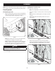
ASSEMBLY 4. Using the harness clip attached to the harness, secure the excess wire to the fender by snapping the harness clip in place as shown in Figure 4. 1. Remove the four hex screws from the bumper. 2. Position the bumper brackets to the inside of the tractor’s frame and secure it in place with the four hex flange screws. See Figure 6.
ASSEMBLY Checking Tire Pressure 3. WARNING NOTE: If the battery is put into service after the date shown on top/side of battery, charge the battery as instructed in the Service section your Operator’s Manual prior to operating the tractor. Equal tire pressure should be maintained at all times. Refer to the tire sidewall for proper pressure. The tires on your tractor may be over-inflated for shipping purposes. Reduce the tire pressure before operating the tractor.
ASSEMBLY Gas and Oil Smart Lawn App Bluetooth® Activation (If Equipped) Fuel Recommendations Use automotive gasoline (unleaded or low leaded to minimize combustion chamber deposits) with a minimum of 87 octane. Gasoline with up to 10% ethanol or 15% MTBE (Methyl Tertiary Butyl Ether) can be used. Never use an oil/gasoline mixture or dirty gasoline. Avoid getting dirt, dust, or water in the fuel tank. DO NOT use E85 gasoline. • Refuel in a well-ventilated area with the engine stopped.
OPERATION Fuel Tank Cap Hour Meter Throttle/Choke Control Lever Ignition Module Forward Drive Pedal Electric PTO Switch Brake Pedal Park Brake/Cruise Control Lever Reverse Drive Pedal Manual PTO Handle Differential Lock Pedal Deck Lift Lever Storage Tray Cup Holder Manual PTO Models Seat Adjustment Lever Transmission Bypass Rod Figure 10 Now that you have set up your riding mower, it’s important to become acquainted with its controls and features. Refer to Differential.
OPERATION Throttle/Choke Control Lever Electric PTO (Blade Engage) Switch The throttle/choke control lever is located on the left side of the tractor’s dash panel. This lever controls the speed of the engine and, when pushed all the way forward, past the detent position closes the choke for cold starting. When set in a given position, the throttle will maintain a uniform engine speed. The PTO switch is located on the dash panel to the right of the LCD Service Minder & Hour Meter.
OPERATION Change Oil • The LCD will display the letters “CHG”, followed by the letters “OIL”, followed by the letters “SOON”, then finally followed by the meter’s accumulated time. “CHG/OIL/SOON/ TIME” will alternate on the display for 7 minutes after the meter reaches 50 hours. This oil service minder interval will occur every 50 hours. Before the interval expires, change the engine oil as instructed in the Maintenance section of the Engine Operator’s Manual.
OPERATION Reverse Caution Mode Driving The Tractor The REVERSE CAUTION MODE position of the ignition module allows the tractor to be operated in reverse with the blades (PTO) engaged. NOTE: Mowing in reverse is not recommended. WARNING Use extreme caution while operating the tractor in the REVERSE CAUTION WARNING Avoid sudden starts, excessive speed and sudden stops. 1. Lightly press the brake pedal to release the parking brake. Move the throttle into the FAST position. 2.
OPERATION Driving On Slopes To disengage the cruise control, lightly press the forward drive pedal or the brake pedal. Refer to the SLOPE GAUGE on page 8 to help determine slopes where you may operate the tractor safely. NOTE: Cruise control can not be set at the tractor’s fastest ground speed. If the operator should attempt to do so, the tractor will automatically decelerate to the fastest optimal mowing ground speed.
OPERATION Engaging the PTO (Manual PTO tractors) 7. When approaching the other end of the strip, slow down or stop before turning. Engaging the PTO transfers power to the cutting deck or other (separately available) attachments. To engage the PTO: 8. Align the mower with an edge of the mowed strip and overlap approximately 3”. 9. Direct the tractor on each subsequent strip to align with a previously cut strip. 1. Move the throttle to the FAST 10. 2.
SERVICE AND MAINTENANCE MAINTENANCE SCHEDULE WARNING Before performing any type of maintenance/service, disengage all controls and stop the engine. Wait until all moving parts have come to a complete stop. Disconnect spark plug wire and ground it against the engine to prevent unintended starting. Always wear safety glasses during operation or while performing any adjustments or repairs. Interval Each use Follow the maintenance schedule given below. This chart describes service guidelines only.
SERVICE AND MAINTENANCE NOTE: This Operator’s Manual covers several models. Tractor features may vary by model. Not all features in this manual are applicable to all tractor models and the tractor depicted may differ from yours. 5. 6. 7. 8. WARNING Before performing any maintenance or repairs, disengage the PTO, set the parking brake, stop the engine and remove the key to prevent unintended starting. 9. 10. 11.
SERVICE AND MAINTENANCE • Storing the Tractor Clean the top of the mower deck, under the spindle covers and belt area. See Figure 17. • • Allow the machine to cool in an open area before storing. Do not park the tractor near any flammable materials (wood, cloth or chemicals) or any open flames or other potential source of ignition (furnace, water heater or any other type of heater). Remove all combustible materials from the tractor before storing. Empty cargo boxes, grass catchers or containers.
SERVICE AND MAINTENANCE 4. Pop open the protective cap on the end of the oil drain valve to expose the drain port. Lubrication WARNING Before lubricating, repairing, or inspecting, always disengage the PTO, set the parking brake, stop the engine and remove the key to prevent unintended starting. Front Wheels OPENED CLOSED Each of the front wheel axles and rims is equipped with a grease fitting.
SERVICE AND MAINTENANCE Deck Wheels 5. The wheels on the deck are equipped with a grease fitting. Lubricate with a No. 2 multi-purpose grease applied with a grease gun after every 25 hours of tractor operation. Leveling the Deck (Side-to-Side) Pivot Points & Linkage Lubricate all the pivot points on the drive system, parking brake and lift linkage at least once a season with light oil. Note: It is not necessary to grease the steering pinion/sector gear interface.
SERVICE AND MAINTENANCE 3. Jump Starting Using the right and left lift rods, raise or lower the necessary side of the deck until both sides are measured at 4” from the pavement. WARNING Adjusting the Deck Wheels Never jump start a damaged or frozen battery. Be certain the vehicles do not touch, and ignitions are off. Do not allow cable clamps to touch. WARNING Keep hands and feet away from the discharge opening of the cutting deck. 1.
SERVICE AND MAINTENANCE Relays and Switches e. There are several safety switches in the electrical system. If a function of the safety interlock system described earlier is not functioning properly, have the electrical system checked by your authorized service dealer. Remove the bow-tie pin that secures the PTO cable to the bracket on the deck, pull back on the PTO cable, then slide it out of the bracket and unhook the spring from the idler bracket. See Figure 25. Cutting Deck Removal 42”Decks 1.
SERVICE AND MAINTENANCE c. Working on the right side of the tractor, insert a 3⁄8” drive ratchet wrench, set to tighten, into square hole found on the idler bracket. See Figure 27. 2. Use the wrench to pivot the deck drive pulley forward. See Figure 28. WARNING Avoid pinching injuries. Never place your fingers on the idler spring or between the belt and a pulley while installing the belt. 3. Carefully remove the belt from around the PTO pulley. 4.
SERVICE AND MAINTENANCE 8. Move the deck lift lever into the top notch to raise the deck lift up and out of the way. 4. CAUTION To properly sharpen the cutting blades, remove equal amounts of metal from both ends of the blades along the cutting edges, parallel to the trailing edge, at a 25°- to 30° angle. Always grind each cutting blade edge equally to maintain proper blade balance. See Figure 32. There is a certain amount of spring tension due to the weight of the deck.
SERVICE AND MAINTENANCE 2. Loosen, but do not remove the flange lock nut on the left idler pulley for 50” and 54” Decks and the right idler pulley for 42” and 46” Decks. See Figure 33 for 42” Decks, Figure 34 for 46” Decks and Figure 35 for 50” and 54” Decks. Hex Screw Flange Lock Nut Flange Lock Nut Figure 35 3. Carefully remove the belt from around the idler pulleys and the spindle pulleys. WARNING Figure 33 Avoid pinching injuries.
SERVICE AND MAINTENANCE 8. Pull the right side of the belt and place the narrow V side of the belt into the PTO pulley. See Figure 39. Figure 39 9. Figure 37 While holding the belt and pulley together, rotate the pulley to the left. Continue holding and rotating the pulley and belt until the belt is fully rolled into the PTO pulley. Changing the Transmission Drive Belt Several components must be removed and special tools used in order to change the tractor’s transmission drive belt.
OFF-SEASON STORAGE WARNING Never store lawn tractor with fuel in tank indoors or in poorly ventilated areas where fuel fumes may reach an open flame, spark, or pilot light as on a furnace, water heater, clothes dryer, or gas appliance. PREPARING THE ENGINE WARNING Gasoline is a toxic substance. Dispose of gasoline properly. Contact your local authorities for approved disposal methods. IMPORTANT: Fuel left in the fuel tank during warm weather deteriorates and will cause serious starting problems. 3.
TROUBLESHOOTING WARNING Before performing any type of maintenance/service, disengage all controls and stop the engine. Wait until all moving parts have come to a complete stop. Disconnect spark plug wire and ground it against the engine to prevent unintended starting. Always wear safety glasses during operation or while performing any adjustments or repairs. This section addresses minor service issues. To locate the nearest authorized Service Center or to schedule service, call 1-888-331-4569.
NOTES 25
ÍNDICE Medidas de seguridad. . . . . . . . . . . . . . . . . . . . . . . . . Página 34 Almacenamiento fuera de temporada . . . . . . . . . Página 61 Montaje . . . . . . . . . . . . . . . . . . . . . . . . . . . . . . . . . . . . . . Página 40 Solución de problemas. . . . . . . . . . . . . . . . . . . . . . . . Página 62 Operación. . . . . . . . . . . . . . . . . . . . . . . . . . . . . . . . . . . . Página 44 Servicio y Mantenimiento . . . . . . . . . . . . . . . . . . . . .
INSTRUCCIONES DE SEGURIDAD ADVERTENCIA PELIGRO La presencia de este símbolo indica que se trata de instrucciones de seguridad importantes que debe respetar para evitar poner en riesgo su seguridad personal y/o material y la de los demás. Lea y cumpla todas las instrucciones de este manual antes de intentar operar esta máquina. Si no respeta estas instrucciones puede provocar lesiones personales.
INSTRUCCIONES DE SEGURIDAD • El silenciador y el motor se calientan y pueden causar quemaduras. No los toque. No haga lo siguiente: • Revise la holgura superior antes de conducir debajo de ramas bajas, cables, cerramientos de puertas, etc., donde el operador puede golpearse o ser tirado de la máquina, lo que podría resultar en lesiones graves. • No gire en pendiente a menos que sea necesario; si lo hace, gire lenta y gradualmente cuesta abajo, si es posible.
INSTRUCCIONES DE SEGURIDAD • En las pendientes, el peso del equipo remolcado puede causar pérdida de tracción y pérdida de control. • Controle periódicamente para asegurarse que las cuchillas se detienen completamente aproximadamente cinco (5) segundos después de accionar el control de desacople. Si las cuchillas no se detienen dentro de este lapso, su máquina debe ser reparada por un profesional de servicio calificado.
INSTRUCCIONES DE SEGURIDAD NO MODIFIQUE EL MOTOR AMORTIGUADOR DE CHISPAS Para evitar lesiones graves o la muerte, no modifique el motor de ninguna manera. Si altera la configuración del regulador, el motor se puede desbocar y funcionar a velocidades que no son seguras. Nunca cambie la configuración de fábrica del regulador del motor.
INSTRUCCIONES DE SEGURIDAD Símbolo Descripción PELIGRO — DISPOSITIVOS DE SEGURIDAD Mantenga los dispositivos de seguridad (guardas, protectores, interruptores, etc.) en su lugar y funcionando. OBSERVADORES Mantenga a los observadores, ayudantes, mascotas y niños por lo menos a 75 pies (23 m.) de la máquina mientras está en funcionamiento. ADVERTENCIA — OPERACIÓN EN PENDIENTES No utilice esta máquina en una pendiente mayor de 15º. No corte en sentido transversal a la pendiente.
INDICADOR DE PENDIENTE (ACEPTAR) Figura 1 15° Pendiente n 15° lí Figura 2 (DEMASIADO ESCARPADO) ua ea d i s c ontin USO DE ESTE PENDIENTE DE CALIBRE PARA DETERMINAR SI UNA PENDIENTE ES DEMASIADO ESCARPADO PARA UNA OPERACIÓN SEGURA! Para comprobar la pendiente, haga lo siguiente: 1. Borrar esta página y doble a lo largo de la línea discontinua. 2. Localizar un objeto vertical sobre o detrás de la pendiente (un poste, un edificio, una valla, un árbol, etc.) 3.
MONTAJE Instale el asiento del operador (si corresponde) NOTA: Las referencias que contiene este manual sobre los lados derecho o izquierdo y trasero o delantero del tractor se hacen siempre desde la posición de operación. Las excepciones, si las hubiere, serán especificadas. Para instalar el asiento proceda de la siguiente manera: NOTA: El asiento se envía con el interruptor de asiento y el contenedor del asiento acoplados. Preparación del tractor 1. Movimiento manual del tractor 1.
MONTAJE 3. Gire el asiento hasta la posición deseada y asegúrelo en su lugar con los tornillos de reborde y las tuercas de seguridad con brida que extrajo antes. Tenga cuidado de no doblar o dañar el cableado mientras instala el asiento. Vea la Figura 3. Baje el deflector del canal de descarga de la plataforma ADVERTENCIA Nunca opere la plataforma de corte sin el deflector del canal de descarga instalado y en posición baja.
MONTAJE Ajuste del asiento 1. ADVERTENCIA Retire la cubierta plástica, si es que está presente, del borne positivo de la batería y una el cable rojo al borne positivo de la batería (+) utilizando el perno y la tuerca hexagonal. Vea la Figura 8. Antes de hacer funcionar el tractor, compruebe que el asiento está enganchado en el tope del asiento. Ponga el freno de mano. Párese detrás de la máquina y tire el asiento hacia atrás hasta que haga clic al calzar en su lugar.
MONTAJE b. Retire las ruedas delanteras y traseras de la plataforma retirando las tuercas de seguridad con brida y los tornillos con reborde que las sujetan a la plataforma. Vea la Figura 9. Gasolina y aceite El depósito de combustible se encuentra en la parte exterior/izquierda del tablero y contiene 3 galones de gas. Extraiga la tapa de combustible girándola hacia la izquierda. Sólo se debe utilizar gasolina limpia, nueva (con menos de 30 días de antigüedad) y sin plomo.
FUNCIONAMIENTO Tapón del depósito de combustible Palanca de control del acelerador/cebador Medidor horario Módulo de encendido Pedal de marcha adelante PTO Switch Pedal de freno Pedal de marcha atrás Palanca del freno de de mano/control de crucero Manija de la PTO Bandeja de almacenamiento Palanca de elevación de la plataforma Portavasos Palanca de ajuste del asiento Manija de la PTO Modelo Varilla de derivación de la transmisión Figura 10 Ahora que ya ha ajustado su tractor cortacésped para el f
FUNCIONAMIENTO Palanca de control del acelerador/cebador Interruptor de la toma de fuerza (PTO) La palanca de control del acelerador/cebador está ubicada del lado izquierdo del tablero de instrumentos del tractor. Esta palanca controla la velocidad del motor y, cuando se la empuja completamente hacia adelante, más allá de la posición de detención, también cierra el cebador para arranques en frío. Cuando se lo coloca en una posición determinada, el acelerador mantiene una velocidad de motor uniforme.
FUNCIONAMIENTO Cambiar el aceite • El LCD mostrará las letras "CHG" (cambiar), seguidas de las letras "OIL" (aceite), seguidas de las letras "SOON" (pronto), y luego finalmente seguidas por el tiempo acumulado del medidor. “CHG/OIL/SOON/TIME” se alternarán en la pantalla durante 7 minutos después de que el medidor llegue a 50 horas. Este intervalo del avisador de servicio de aceite se producirá cada 50 horas.
FUNCIONAMIENTO Modo marcha atrás con precaución Conducción del tractor ADVERTENCIA La posición MODO MARCHA ATRÁS CON PRECAUCIÓN del módulo de encendido permite operar el tractor marcha atrás con la (PTO) de las cuchillas activada. Evite arrancar súbitamente, desarrollar excesiva velocidad y detenerse de repente. NOTA: No se recomienda cortar el césped en marcha atrás. ADVERTENCIA Tenga mucho cuidado cuando opere el tractor en MODO DE PRECAUCIÓN EN MARCHA ATRÁS.
FUNCIONAMIENTO Operación en pendientes Para desactivar el control de crucero, presione suavemente el pedal de marcha adelante o el pedal de freno. Consulte la sección INDICADOR DE PENDIENTE en la página 8 para determinar en qué pendientes puede operar el tractor de manera segura. NOTA: El control de crucero no se puede fijar en la velocidad absoluta más rápida del tractor. Si el operador intentara hacerlo, el tractor se desacelerará automáticamente a la velocidad de corte absoluta óptima y más rápida.
FUNCIONAMIENTO Conexión de la toma de fuerza (Manual PTO de tractor) 6. Al conectar la PTO se suministra energía a la plataforma de corte y a otros accesorios (disponibles por separado). Para conectar la PTO: 1. Mueva el acelerador a la posición FAST 2. Empuje la palanca de la PTO hacia adelante a la posición de activación (ON). Vea la Figura 13. Presione lentamente el pedal de marcha adelante con el pie derecho hasta alcanzar la velocidad deseada.
SERVICIO Y MANTENIMIENTO PROGRAMA DE MANTENIMIENTO ADVERTENCIA Antes de realizar cualquier tipo de mantenimiento o servicio, desactive todos los controles y detenga el motor. Espere a que se detengan completamente todas las piezas móviles. Desconecte el cable de la bujía y póngalo haciendo masa contra el motor para evitar que se encienda accidentalmente. Utilice siempre anteojos de seguridad durante el funcionamiento o mientras ajusta o repara este equipo.
SERVICIO Y MANTENIMIENTO calificadoNOTA: Este manual de operación cubre distintos modelos. Las características del tractor pueden variar según los modelos. No todas las características que se incluyen en este manual se aplican a todos los modelos de tractor y la máquina que se ilustra aquí puede diferir de la suya. ADVERTENCIA Antes de realizar tareas de mantenimiento o reparaciones, desconecte la PTO, ponga el freno de mano, apague el motor y retire la llave para evitar el encendido accidental del motor.
SERVICIO Y MANTENIMIENTO • Clean bajo el capó. Colector de escape, alrededor de fusibles, todo el cableado y arneses, tubo silenciador, escudo de silenciador, pantallas de admisión del motor y las aletas de refrigeración, etc. Vea la Figura 16. • Limpia alrededor y cerca de la transmisión, el eje y el área del ventilador. Vea la Figura 18. Rueda no muestra por claridad Figura 16 • Limpiar la parte superior de la plataforma de corte, bajo las sábanas de husillo y área de la correa. Vea la Figura 17.
SERVICIO Y MANTENIMIENTO Transmisión hidrostática Cambio de aceite del motor ADVERTENCIA Si el motor ha estado en funcionamiento recientemente, el motor, el silenciador y las superficies metálicas circundantes estarán calientes y pueden causar quemaduras en la piel. Tenga precaución para evitar quemaduras. Para realizar el cambio de aceite, proceda de la siguiente manera: 1. Haga funcionar el motor por un período corto para calentar el aceite del motor. El aceite fluirá mejor y limpiará las impurezas.
SERVICIO Y MANTENIMIENTO Ruedas de la plataforma 5. Las ruedas de la plataforma están equipadas con dispositivo de engrase. Lubrique con una grasa multiuso No. 2 aplicada con una pistola de engrase cada 25 horas de funcionamiento del tractor. Nivelación de la plataforma (de lado a lado) Puntos de pivote y varillaje Para bajar el frente de la plataforma, afloje la tuerca exterior y luego afloje (rosca hacia afuera) la tuerca, alejándola del soporte de suspensión delantera. Consulte la Figura 22.
SERVICIO Y MANTENIMIENTO Ajuste de las ruedas de la plataforma Arranque con cables de puente ADVERTENCIA ADVERTENCIA Mantenga las manos y los pies alejados de la abertura de descarga de la plataforma de corte. NOTA: Las ruedas de la plataforma constituyen un mecanismo para el cuidado del césped y no fueron diseñadas para soportar el peso de la plataforma de corte.
SERVICIO Y MANTENIMIENTO Fusible e. Extraiga el pasador de chaveta que sujeta el cable de la PTO al soporte de la plataforma, tire hacia atrás del cable de la PTO, luego deslícelo fuera del soporte y desenganche el resorte del soporte intermedio. Vea la Figura 25. f. Trabajando en el lado derecho del tractor, inserte una llave de trinquete de 3⁄8”, regulada para ajustar, en el orificio cuadrado del soporte intermedio. Vea la Figura 26.
SERVICIO Y MANTENIMIENTO c. Trabajando en el lado derecho del tractor, inserte una llave de trinquete de 3⁄8”, regulada para ajustar, en el orificio cuadrado del soporte intermedio. Vea la Figura 27. ADVERTENCIA Evite las lesiones por compresión. Al instalar la correa, no coloque nunca los dedos en el resorte intermedio o entre la correa y una polea. 3. Extraiga con cuidado la correa de alrededor de la polea de la PTO. 4.
SERVICIO Y MANTENIMIENTO 8. 4. Mueva la palanca de elevación de la plataforma a la muesca superior para levantar el elevador de la plataforma y sacarlo del camino. PRECAUCIÓN Hay cierta tensión de los resortes debido al peso de la plataforma. Al retirar el varillaje de elevación de la plataforma, la tensión de los resortes pasará de la plataforma a la manija de elevación de plataforma y retrocederá a su posición original. 9.
SERVICIO Y MANTENIMIENTO 2. Afloje , pero no quite la tuerca de seguridad con brida de la polea tensora izquierda de 54" Las cubiertas y la polea loca adecuado para 42" y 46" de skate . Vea la Figura 33 para 42" Cubiertas, Figura 34 para 46" Las cubiertas y la Figura 35 para 54" Cubiertas Tornillo hexagonal Tornillo hexagonal Tuerca de seguridad con brida Tuerca de seguridad con brida 3. Figura 35 Saque con cuidado la correa de alrededor de las poleas locas y las poleas de los husillos.
SERVICIO Y MANTENIMIENTO 5. Vuelva a ajustar las poleas locas. 6. Vuelva a montar las cubiertas de los husillos se fueron retiradas después del paso 1. 7. Reinstale la plataforma, comprobando que la correa se ha pasado alrededor de las poleas como se indica. 8. Tire del lado derecho de la correa y coloque el lado V angosto de la correa en la polea de la PTO. Vea la Figura 39. Figura 37 9. Figura 39 Mientras sostiene la correa y la polea juntas, rote la polea hacia la izquierda.
ALMACENAMIENTO FUERA DE TEMPORADA ADVERTENCIA Nunca almacene tractor de césped con combustible en el tanque en un espacio cerrado o en áreas con poca ventilación, donde los gases del combustible puedan alcanzar el fuego, chispas o una luz piloto como la que tienen algunos hornos, calentadores de agua, secadores de ropa o algún otro dispositivo a gas. PREPARACIÓN DEL MOTOR d. IMPORTANTE: El combustible que queda en el tanque cuando hace calor se deteriora y ocasiona graves problemas de encendido.
SOLUCIÓN DE PROBLEMAS ADVERTENCIA Antes de realizar cualquier tipo de mantenimiento o servicio, desactive todos los controles y detenga el motor. Espere a que se detengan completamente todas las piezas móviles. Desconecte el cable de la bujía y póngalo haciendo masa contra el motor para evitar que se encienda accidentalmente. Utilice siempre anteojos de seguridad durante el funcionamiento o mientras ajusta o repara este equipo. Esta sección aborda problemas menores de servicio.
NOTAS 63
CRAFTSMAN® is a registered trademark of Stanley Black & Decker, Inc., used under license. CRAFTSMAN® es una marca registrada de Stanley Black & Decker, Inc., utilizada bajo licencia. © 2018 CRAFTSMAN U.S. & Canada Only CRAFTSMAN.com Product Manufactured by (Producto fabricado por): MTD LLC, P.O.