INSTRUCTION MANUAL | MANUAL DE INSTRUCTIONES T100 SERIES LAWN TRACTOR/TRACTORES CORTACÉSPED Model Nos. CMXGRAM1130036 CMXGRAM1130037 CMXGRAM1130038 CMXGRAM1130039 CMXGRAM1130041 CMXGRAM1130042 CMXGRAM7821242 CMXGRAM7831829 IF YOU HAVE QUESTIONS OR COMMENTS, CONTACT US. SI TIENE DUDAS O COMENTARIOS, CONTÁCTENOS. 1-888-331-4569 CRAFTSMAN® is a registered trademark of Stanley Black & Decker, Inc., used under license. CRAFTSMAN® es una marca registrada de Stanley Black & Decker, Inc., utilizada bajo licencia.
TABLE OF CONTENTS Safe Operation Practices . . . . . . . . . . . . . . . . . . . . . . . . .Page 3 Off-Season Storage. . . . . . . . . . . . . . . . . . . . . . . . . . . . . Page 30 Assembly . . . . . . . . . . . . . . . . . . . . . . . . . . . . . . . . . . . . . . . .Page 9 Troubleshooting . . . . . . . . . . . . . . . . . . . . . . . . . . . . . . . .Page 31 Operation . . . . . . . . . . . . . . . . . . . . . . . . . . . . . . . . . . . . . .Page 15 Español . . . . . . . . . . . . . . . . . . . . .
SAFETY INSTRUCTIONS WARNING DANGER This symbol points out important safety instructions which, if not followed, could endanger the personal safety and/or property of yourself and others. Read and follow all instructions in this manual before attempting to operate this machine. Failure to comply with these instructions may result in personal injury. When you see this symbol, HEED ITS WARNING! This machine was built to be operated according to the safe operation practices in this manual.
SAFETY INSTRUCTIONS • Check overhead clearances carefully before driving under low hanging tree branches, wires, door openings etc., where the operator may be struck or pulled from the machine, which could result in serious injury. Do Not: • Do not turn on slopes unless necessary; then, turn slowly and gradually downhill, if possible. • Disengage all attachment clutches and depress the brake pedal completely before attempting to start engine.
SAFETY INSTRUCTIONS • On slopes, the weight of the towed equipment may cause loss of traction and loss of control. • Always use extra caution when towing with a machine capable of making tight turns (e.g. “zero-turn” ride-on mower). Make wide turns to avoid jack-knifing. • Travel slowly and allow extra distance to stop. • Do not coast downhill. • Periodically check to make sure the blades come to complete stop within approximately (5) five seconds after operating the blade disengagement control.
SAFETY INSTRUCTIONS DO NOT MODIFY ENGINE SPARK ARRESTOR To avoid serious injury or death, do not modify engine in any way. Tampering with the governor setting can lead to a runaway engine and cause it to operate at unsafe speeds. Never tamper with factory setting of engine governor.
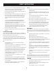
SAFETY INSTRUCTIONS Symbol Description DANGER — SAFETY DEVICES Keep safety devices (guards, shields, switches, etc.) in place and working. BYSTANDERS Keep bystanders, helpers, children and pets at least 75 feet from the machine while it is in operation. WARNING— SLOPE OPERATION Do not operate this machine on a slope greater than 15 degrees. Do not mow across slopes. Mow up and down slopes no greater than 15 degrees. Avoid sudden turns. Use low speed.
Figure 1 ashed 15° d line Figure 2 (TOO STEEP) Slopes are a major factor related to tip-over and roll-over accidents which can result in severe injury or death. Do not operate machine on slopes in excess of 15 degrees. All slopes require extra caution. If you cannot back up the slope or if you feel uneasy on it, do not mow it. Always mow up and down the face of slopes, never mow across the face of slopes.
ASSEMBLY & SET-UP Contents of Carton • Lawn Tractor (1) • Steering Wheel (1) -- Cup Washer (1) & Hex Bolt (1) • Operator’s Manual (1) • Ignition Key (2) • Seat (1) Engine Operator’s Manual (1) • Plastic Oil Drain Sleeve (1) † • Dash Shroud (1) † • Fast Start Guide (1)† • Oil Drain Hose (1) † • Deck Wash Nozzle (1) † • Parts/Warranty Document (1) • Hood Scoop (1) † • Hose Coupler (1) † • Product Registration Card (1) † • † — If Equipped NOTE: This Operator’s Manual covers several
ASSEMBLY & SET-UP 1. Locate the hydrostatic bypass rod in the rear of the tractor. See Figure 2. Connecting the Battery Cables WARNING CALIFORNIA PROPOSITION 65 WARNING: Battery posts, terminals, and related accessories contain lead and lead compounds, chemicals known to the State of California to cause cancer and reproductive harm. Wash hands after handling. CAUTION When attaching battery cables, always connect the POSITIVE (Red) wire to its terminal first, followed by the NEGATIVE (Black) wire.
ASSEMBLY & SET-UP Shipping Brace Removal Attaching the Steering Wheel 1. WARNING Make sure the tractor’s engine is OFF, remove the ignition key, and set the parking brake before removing the shipping brace. Refer to the Controls & Operations section on page 16 for instructions on how to set the parking brake. If the steering wheel (a) for your tractor did not come attached, the hardware for attaching it has been packed within the steering wheel (a), beneath the steering wheel cap (b).
ASSEMBLY & SET-UP 1. Remove the seat adjustment knob (a) from the bottom of the seat (b). See Figure 6. 5. To adjust the position of the seat, remove the adjustment knob (a) on the bottom of the seat (b). Slide the seat (b) forward or backward as desired. Reinstall the adjustment knob (a). See Figure 7. Dash Shroud (If Equipped) 1. If the dash shroud (a) was shipped loose, the hardware for attaching the dash shroud (a) is shipped installed in the dash shroud (a).
ASSEMBLY & SET-UP 3. Gasoline Reinstall the fuel cap. The gasoline tank is located under the hood. Do not overfill. STOP WARNING Use extreme care when handling gasoline. Gasoline is extremely flammable and the vapors are explosive. Never fuel machine indoors or while the engine is hot or running. Extinguish cigarettes, cigars, pipes, and other sources of ignition. NOTE : Purchase gasoline in small quantities.
ASSEMBLY & SET-UP b. Remove the front and rear deck gauge wheels (a) by removing the lock nuts (b) and shoulder screws (c) which secure them to the deck. See Figure 11. Attaching the Hood Scoop (If Necessary/If Equipped) 1. 2. 3. 4. On some tractors, a hood scoop may be included. If the hood scoop was not installed on the hood of your tractor at the factory, refer to the following steps to install the hood scoop: Cut the cable ties securing the hood scoop to the tractor.
OPERATION Ignition Switch Module Throttle/Choke Control Lever Parking Brake Lever /Speed Control † Brake Pedal †/Clutch-Brake Pedal † Drive Pedal † Speed Control Lever † Shift Lever † Deck Lift Lever PTO Lever Cup Holder Figure 13 Now that you have set up your riding mower, it’s important to become acquainted with its controls and features. Refer to Figure 13.
OPERATION CVT 7 The speed control lever, located on the lower left side of the lawn tractor’s dash console, allows you to regulate the ground speed of the lawn tractor. 5 4 3 2 1 The ground speed is controlled with the drive pedal. The further forward that the pedal is pivoted, the faster the lawn tractor will travel. The pedal will return to its original position when it’s not depressed. Refer to Driving the Lawn Tractor on page 19 for detailed instructions regarding the drive pedal.
OPERATION To use the REVERSE CAUTION MODE: WARNING Never leave a running machine unattended. Always disengage PTO, move shift lever into neutral position, set parking brake, stop engine and remove key to prevent unintended starting. IMPORTANT: The operator MUST be seated in the lawn tractor seat. 1. Start the engine as instructed on page 18. 2. Turn the key from the NORMAL DRIVING MODE (Green) position to the REVERSE CAUTION MODE (Yellow) position of the ignition switch module. See Figure 15.
OPERATION Setting the Cutting Height Driving the Lawn Tractor 1. Select the height position of the cutting deck by placing the deck lift lever in any of the five different cutting height notches on the right side of the fender. IMPORTANT: First-time operators should become completely familiar with the lawn tractor’s operation and controls before operating the lawn tractor in higher speed positions. 2.
OPERATION CVT 1. Depress the clutch-brake pedal to release the parking brake and let the pedal up. 2. Move the throttle lever into the FAST (rabbit) position. 3. Place the shift lever in either the FORWARD (F) or REVERSE (R) position. WARNING Before leaving the operator’s position for any reason, disengage the blades, place the shift lever in NEUTRAL (N), engage the parking brake, shut engine OFF and remove the key.
OPERATION Using the Deck Lift Lever To raise the cutting deck, move the deck lift lever to the left, then place it in the notch best suited for your application. Refer to Setting the Cutting Height on page 15. Mowing WARNING To help avoid blade contact or a thrown object injury, keep bystanders, helpers, children and pets at least 75 feet from the machine while it is in operation. Stop machine if anyone enters the area.
SERVICE AND MAINTENANCE MAINTENANCE SCHEDULE WARNING Before performing any type of maintenance/service, disengage all controls and stop the engine. Wait until all moving parts have come to a complete stop. Disconnect spark plug wire and ground it against the engine to prevent unintended starting. Always wear safety glasses during operation or while performing any adjustments or repairs. Interval Each Use Follow the maintenance schedule given below. This chart describes service guidelines only.
SERVICE AND MAINTENANCE 4. Maintenance Attach the hose coupler to the water port on your decks surface. See Figure 1. WARNING Before performing any maintenance or repairs, disengage PTO, move shift lever into neutral position, set parking brake, stop engine and remove key to prevent unintended starting. WARNING If the engine has been recently run, the engine, muffler and surrounding metal surfaces will be hot and can cause burns to the skin. Exercise caution to avoid burns.
SERVICE AND MAINTENANCE • Clean under the hood. Exhaust manifold, around fuses, all wiring and harnesses, muffler pipe, muffler shield, engine intake screens and cooling fins, etc. See Figure 2. • Debris can accumulate anywhere on the rider, especially on horizontal surfaces. Additional cleaning may be necessary when mowing in dry conditions or when mulching. • Fuel leaks/spills, oil leaks/spills and excess lubrication can also become collections sites for debris.
SERVICE AND MAINTENANCE 4. Remove the oil fill cap/dipstick from the oil fill tube. 5. 5. Push the oil drain hose (provided) onto the oil drain port. Route the opposite end of the hose into an appropriate oil collection container with at least a 2.5 quart capacity, to collect the used oil. 6. 6. Slightly push in on the oil drain valve and rotate counter-clockwise to open and allow the flow of oil. See Figure 5. 7.
SERVICE AND MAINTENANCE 4. 5. 6. 7. Push the bulb inward and turn counter-clockwise to remove from the socket. Align a locking post of the bulb base with the notch in the socket, then push the bulb inward and turn clockwise to lock. See Figure 7. Align the socket tab with the notch of the reflector housing; then push the socket inward and turn as necessary to lock the socket in the housing. Connect the wire harness leads to the appropriate socket terminals.
SERVICE AND MAINTENANCE 3. Removing the Battery To remove the battery, pull outward and then up on the battery hold-down bracket. See Figure 8. Locate the jam nut and lock nut on the front side of the stabilizer bracket. See Figure 9. Figure 9 Figure 8 Fuse One 20A fuse is installed in your tractor’s wiring harness to protect the tractor’s electrical system from damage caused by excessive amperage. 4. After loosening the jam nut: 5. Tighten the lock nut to raise the front of the deck; 6.
SERVICE AND MAINTENANCE 3. Loosen, but do NOT remove, the hex cap screw (a) on the left deck hanger bracket. See Figure 10. 3. (a) Remove the belt-keeper rod (a), from around the tractor’s engine pulley, by removing the self-tapping screw (b) that secures it. See Figure 11. (c) (b) (a) Figure 10 4. 5. Balance the deck by using a wrench to turn the adjustment gear (found immediately behind the hex cap screw just loosened) clockwise/up or counter-clockwise/down.
SERVICE AND MAINTENANCE 7. Move the deck lift lever into the top notch on the right fender to raise the deck lift arms up and out of the way. 8. Remove the bow-tie pin (a) securing the deck stabilizer rod (b) to the deck. Slide the deck lift rod from the mounting weldment on the deck as seen in Figure 13. Cutting Deck Installation To install the deck, reverse the Deck Removal instructions on page 27-28. Tires WARNING Never exceed the maximum inflation pressure shown on the sidewall of the tire.
SERVICE AND MAINTENANCE 3. Remove the hex flange nut that secures the blade to the spindle assembly. See Figure 15. 4. To properly sharpen the cutting blades, remove equal amounts of metal from both ends of the blades along the cutting edges, parallel to the trailing edge, at a 25° to 30° angle. Changing the Deck Belt WARNING Be sure to shut the engine OFF, remove the key, disconnect the spark plug wire(s) and ground against the engine to prevent unintended starting before removing the belt.
OFF-SEASON STORAGE WARNING Never store lawn tractor with fuel in tank indoors or in poorly ventilated areas where fuel fumes may reach an open flame, spark, or pilot light as on a furnace, water heater, clothes dryer, or gas appliance. Preparing the Engine Draining the Fuel IMPORTANT: Fuel left in the fuel tank during warm weather deteriorates and will cause serious starting problems. 1.
TROUBLESHOOTING WARNING Before performing any type of maintenance/service, disengage all controls and stop the engine. Wait until all moving parts have come to a complete stop. Disconnect spark plug wire and ground it against the engine to prevent unintended starting. Always wear safety glasses during operation or while performing any adjustments or repairs. This section addresses minor service issues. To locate the nearest authorized Service Center or to schedule service, call 1-888-331-4569.
Notes Page This page intentionally left blank. Use this page to make any notes regarding your tractor.
Notes Page This page intentionally left blank. Use this page to make any notes regarding your tractor.
ÍNDICE Medidas de seguridad . . . . . . . . . . . . . . . . . . . . . . . . .Página 34 Almacenamiento fuera de temporada . . . . . . . . .Página 61 Montaje . . . . . . . . . . . . . . . . . . . . . . . . . . . . . . . . . . . . . .Página 40 Solución de problemas . . . . . . . . . . . . . . . . . . . . . . . .Página 62 Operación . . . . . . . . . . . . . . . . . . . . . . . . . . . . . . . . . . . .Página 46 Servicio y Mantenimiento . . . . . . . . . . . . . . . . . . . . .
INSTRUCCIONES DE SEGURIDAD ADVERTENCIA PELIGRO La presencia de este símbolo indica que se trata de instrucciones importantes de seguridad que se deben respetar para evitar poner en peligro su seguridad personal y/o material y la de otras personas. Lea y siga todas las instrucciones de este manual antes de poner en funcionamiento esta máquina. Si no respeta estas instrucciones podría provocar lesiones personales.
INSTRUCCIONES DE SEGURIDAD • • • • • • • • • Nunca deje la máquina en funcionamiento sin vigilancia. Apague siempre las cuchillas, coloque el freno de mano, detenga el motor y retire la llave antes de bajarse del vehículo. Tenga sumo cuidado al cargar o descargar la máquina en un remolque o camión. Esta unidad no debe conducirse en ascenso o descenso de rampas, porque podría ladearse y provocar lesiones personales graves.
INSTRUCCIONES DE SEGURIDAD No permita nunca que los niños menores de 14 años utilicen esta máquina. Los niños de 14 años en adelante deben leer y entender las instrucciones de operación y normas de seguridad contenidas en este manual, y en la máquina y deben ser entrenados y supervisados por un adulto. REMOLQUE • • • • • • • Remolque únicamente con una máquina que cuente con un enganche diseñado para remolcar. No acople equipo remolcado excepto en el punto de enganche.
INSTRUCCIONES DE SEGURIDAD • • • • • • Repare el daño antes de arrancar y utilizar la máquina. Nunca trate de hacer ajustes o reparaciones a la máquina mientras el motor está en marcha. Los componentes del colector de césped y la cubierta de descarga, están sujetos a desgaste y daños que podrían dejar expuestas partes en movimiento o permitir que se arrojen objetos.
INSTRUCCIONES DE SEGURIDAD Symbol Description PELIGRO— DÉ EL CORTE DE PIE Guarde manos y pies lejos de hacer girar partes. PELIGRO— DÉ EL CORTE DE PIE Mire siempre hacia abajo y hacia atrás antes y mientras retrocede, para evitar accidentes en off.. PELIGRO— ESCOMBROS LANZADOS Quite objetos que pueden ser lanzados por la lámina en cualquier dirección. Lleve gafas de seguridad. DISPOSITIVOS DE SEGURIDAD - PELIGRO Mantenga los dispositivos de seguridad (guardas, escudos, interruptores, etc.
PENDIENTE DE CALIBRE (ACEPTAR) Figura 1 15° Pendiente ne 15° lí Figura 2 (DEMASIADO ESCARPADO) nua a d i s c onti USO DE ESTE PENDIENTE DE CALIBRE PARA DETERMINAR SI UNA PENDIENTE ES DEMASIADO ESCARPADO PARA UNA OPERACIÓN SEGURA! Para comprobar la pendiente, haga lo siguiente: 1. Borrar esta página y doble a lo largo de la línea discontinua. 2. Localizar un objeto vertical sobre o detrás de la pendiente (un poste, un edificio, una valla, un árbol, etc.) 3.
MONTAJE Y CONFIGURACIÓN Contenido de la caja • Tractor cortacésped (1) • Volante (1) -- Arandela cóncava (1) y Perno hexagonal (1) • Manual del Operador (1) • Llave de contacto (2) • Asiento (1) • Manual del Operador del Motor (1) • Manga plástica para drenar aceite (1) † • Cubierta de instrumentos (1) † • Guía de inicio rápido (1)† • Manguera para drenar aceite (1) † • Pico de lavado de la plataforma (1) † • Documento de Garantía/Piezas (1) • Toma de aire del capó (1) † • Acoplad
MONTAJE Y CONFIGURACIÓN NOTA: El borne positivo de la batería está marcado como Pos (+). El borne negativo de la batería está marcado como Neg (-). 1. Extracción de la traba de seguridad Retire la cubierta plástica, si está presente, del borne positivo de la batería y una el cable rojo al borne positivo de la batería (+) utilizando el perno (a) y la tuerca hexagonal (b). Consulte la Figura 2.
MONTAJE Y CONFIGURACIÓN Fijación del volante Instalación del asiento 1. Si su tractor no traía el asiento instalado de fábrica, consulte los pasos siguientes: Si su tractor no traía el volante (a) instalado, los herrajes para instalarlo se han embalado dentro del volante (a), debajo de la tapa del volante (b). Con cuidado y usando una palanca, extraiga la tapa del volante (b) y retire la arandela cóncava (c) y el perno hexagonal (d). Consulte la Figura 4.
MONTAJE Y CONFIGURACIÓN NOTA: Asegúrese que las dos lengüetas del asiento se enganchan en el soporte de pivote del asiento, como se muestra en el recuadro inferior derecho de la Figura 6. 4. Seleccione la posición deseada del asiento (b) y fíjelo con la perilla de ajuste (a) que retiró en el Paso 1. Consulte la Figura 6. 5. Para ajustar la posición del asiento, retire la perilla de ajuste (a) que está en la parte inferior del asiento (b).
MONTAJE Y CONFIGURACIÓN 2. Cargue el depósito de combustible con gasolina. Sólo se debe utilizar gasolina limpia, nueva (con menos de 30 días de antigüedad) y sin plomo. Llene el depósito hasta la base del cuello de llenado dejando espacio para la dilatación del combustible. NO LLENE EL DEPÓSITO DE COMBUSTIBLE AL MÁXIMO. Consulte la Figura 8. 2. Cargue el depósito de combustible con gasolina. Sólo se debe utilizar gasolina limpia, nueva (con menos de 30 días de antigüedad) y sin plomo.
MONTAJE Y CONFIGURACIÓN b. Retire las ruedas de calibración delanteras y traseras (a) retirando las tuercas de sujeción (b) y los tornillos con reborde (c) que las sujetan a la plataforma. Consulte la Figura 10. 5. Instale la toma de aire sobre el capó del tractor y fije desde abajo con los cuatro tornillos que retiró en el Paso 2. Movimiento manual del tractor Los modelos con CVT se pueden poner en la posición NEUTRAL (N) cuando es necesario mover el tractor manualmente.
FUNCIONAMIENTO Palanca de control del acelerador/cebador Pedal de freno †/Pedal de embrague-freno † Palanca de control de velocidad † Módulo del interruptor de contacto Palanca del freno de mano /Control de velocidad † Pedal de marcha † Palanca de cambios † Palanca de elevación de la plataforma Portavasos Palanca de PTO Figura 13 Ahora que ya ha ajustado su tractor cortacésped para el funcionamiento, es importante familiarizarse con sus controles y características. Consulte la Figura 13.
FUNCIONAMIENTO Palanca de cambios CVT 7 La palanca de control de velocidad, ubicada del lado izquierdo inferior del tablero de instrumentos del tractor, le permite regular la velocidad absoluta del tractor cortacésped. Para utilizarla, presione el pedal del embrague-freno, saque la palanca de la muesca del freno de estacionamiento y llévela hacia adelante para aumentar la velocidad de piso del tractor.
FUNCIONAMIENTO Módulo del interruptor de contacto Interruptores de enclavamiento de seguridad El interruptor de contacto se usa para arrancar el motor. Inserte la llave en el interruptor de contacto y gírela hacia la derecha a la posición ARRANQUE. Suelte la llave en la posición ENCENDIDO una vez que haya arrancado el motor. Consulte la Figura 14A. El motor funcionará con los faros delanteros ENCENDIDOS. Este tractor está equipado con un sistema de enclavamiento de seguridad para protección del operador.
FUNCIONAMIENTO 2. Gire la llave desde la posición MODO MARCHA NORMAL (verde) hasta la posición de MODO PRECAUCIÓN MARCHA ATRÁS (amarillo) del módulo del interruptor de contacto. Consulte la Figura 15. Ajuste de la altura de corte 1. Seleccione la altura de corte de la cubierta de corte colocando la palanca de elevación de la cubierta en cualquiera de las cinco muescas de altura de corte, en el lado derecho del guardabarros. Luz indicadora 2.
FUNCIONAMIENTO 4. Conducción del tractor cortacésped IMPORTANTE: Los operadores primerizos deben familiarizarse por completo con el funcionamiento y los controles del tractor cortacésped antes de hacerlo funcionar a velocidades más altas, IMPORTANTE: Los operadores primerizos deben usar las posiciones de velocidad 1 o 2.
FUNCIONAMIENTO Estacionamiento del tractor cortacésped Corte de césped IMPORTANTE: Cuando pare el tractor por cualquier motivo en un área de césped: 1. ADVERTENCIA Coloque la palanca de cambios/control de velocidad en N (neutral), 2. Ponga el freno de mano. 3. Apague el motor y retire la llave. Eso reducirá al mínimo la posibilidad de “quemar” el césped con el escape caliente del motor en funcionamiento del tractor cortacésped.
SERVICIO Y MANTENIMIENTO PROGRAMA DE MANTENIMIENTO Siga el cronograma de mantenimiento que se presenta a continuación. En esta tabla sólo describen pautas de servicio. Utilice la columna Registro de Servicio para hacer el seguimiento de las tareas de mantenimiento completadas. Para ubicar el Centro de servicio de reparaciones y piezas más cercano o para programar el servicio de mantenimiento o reparación, simplemente comuníquese al teléfono 1-888-331--4569.
SERVICIO Y MANTENIMIENTO 44. Mantenimiento Una el acople de la manguera al puerto de agua que se encuentra en la superficie de la plataforma. Vea la Figura 16. ADVERTENCIA Antes de realizar tareas de mantenimiento o reparaciones, desconecte la potencia de arranque (PTO), mueva la palanca de cambios a la posición neutral, coloque el freno de mano, apague el motor y retire la llave, para evitar el arranque accidental del motor.
SERVICIO Y MANTENIMIENTO • Clean bajo el capó. Colector de escape, alrededor de fusibles, todo el cableado y arneses, tubo silenciador, escudo de silenciador, pantallas de admisión del motor y las aletas de refrigeración, etc. Vea la Figura 17. • Los residuos pueden acumularse en cualquier lugar en el tractor, especialmente en superficies horizontales. Limpieza adicional puede ser necesaria cuando la siega en condiciones secas o cuando acolchado.
SERVICIO Y MANTENIMIENTO 3. Abra la tapita protectora del extremo de la válvula de drenaje para visualizar el orificio de drenaje. Consulte el recuadro de Figura 20. 4. Coloque el extremo pequeño de la manga de drenado en el cárter de aceite. Consulte la Figura 21. Rotar en sentido contrario a las agujas del reloj para abrir ABIERTO CERRADO Figura 20 4. Retire el tapón de llenado de aceite/la varilla de nivel de aceite del tubo de llenado. 5.
SERVICIO Y MANTENIMIENTO 3. Gire la boquilla conectora aproximadamente un 1⁄4 de vuelta para alinear lengüeta con la muesca de la caja del reflector; luego retire el foco y la boquilla conectora de la caja del reflector. Consulte la Figura 22. • Siempre mantenga limpios y libres de acumulación de elementos corrosivos los cables y los bornes de la batería. • Después de limpiar la batería y los bornes, aplique una capa delgada de vaselina o grasa a ambos bornes.
SERVICIO Y MANTENIMIENTO 4. Haga la conexión final al bloque del motor del tractor, alejado de la batería. Acople a una pieza sin pintura para garantizar una buena conexión. PRECAUCIÓN Si la batería auxiliar está instalada en un vehículo (un auto, un camión) NO ponga en marcha el motor del vehículo cuando arranque su tractor con un puente. 5. Ponga en marcha el tractor según se indica en la página 18. 6.
SERVICIO Y MANTENIMIENTO 3. Afloje, pero NO extraiga, el tornillo hexagonal (a) ubicado en la ménsula de suspensión izquierda de la plataforma. Consulte la Figura 25. 3. (a) Retire la varilla del guardacorrea (a), alrededor de la polea del motor del tractor, sacando el tornillo autoroscante (b) que lo fija. Consulte la Figura 26. (c) (b) (a) Figura 25 4. 5.
SERVICIO Y MANTENIMIENTO 7. 8. Mueva la palanca de elevación de la plataforma dentro de la muesca superior del guardabarros derecho para levantar los brazos de elevación de la plataforma y sacarlos del camino. Extraiga el pasador de chaveta curvo (a) que sujeta la varilla estabilizadora (b) a la plataforma Deslice la varilla de elevación de la plataforma lejos de la soldadura de montaje de la plataforma como se ve en la Figura 28.
SERVICIO Y MANTENIMIENTO 3. Extraiga la tuerca de brida hexagonal que asegura la cuchilla al montaje del husillo. Consulte la Figura 30. 4. Para afilar las cuchillas de corte correctamente, extraiga cantidades iguales de metal de ambos extremos de las cuchillas a lo largo de los bordes cortantes, paralelo al borde de caída, a un ángulo de 25° a 30°.
ALMACENAMIENTO FUERA DE TEMPORADA ADVERTENCIA Nunca almacene tractor de césped con combustible en el tanque en un espacio cerrado o en áreas con poca ventilación, donde los gases del combustible puedan alcanzar el fuego, chispas o una luz piloto como la que tienen algunos hornos, calentadores de agua, secadores de ropa o algún otro dispositivo a gas. Preparación del motor IMPORTANTE: El combustible que queda en el tanque cuando hace calor se deteriora y ocasiona graves problemas de encendido.
SOLUCIÓN DE PROBLEMAS ADVERTENCIA Antes de realizar cualquier tipo de mantenimiento o servicio, desenganche todos los controles y detenga el motor. Espere a que se detengan completamente todas las piezas móviles. Desconecte el cable de la bujía y póngalo haciendo masa contra el motor para evitar que se encienda accidentalmente. Utilice siempre anteojos de seguridad durante el funcionamiento o mientras ajusta o repara este equipo. Esta sección aborda problemas menores de servicio.
Notes Page 63
CRAFTSMAN® is a registered trademark of Stanley Black & Decker, Inc., used under license. CRAFTSMAN® es una marca registrada de Stanley Black & Decker, Inc., utilizada bajo licencia. © 2018 CRAFTSMAN U.S. & Canada Only CRAFTSMAN.com Product Manufactured by (Producto fabricado por): MTD LLC, P.O.