
How to Guide


Ten-Foot Rail Extension Kit
Model CMXZDCG4910
®
BEFORE YOU BEGIN:
• The trolley must be in down (closed door) position during assembly and
installation. If you have a completely installed garage door opener, the rail/
opener assembly must be taken down. The UP and DOWN travel must be
readjusted after installation.
• Opener hanging brackets will require repositioning and the addition of an extra
bracket for stability due to increased rail length.
• This may require two people for installation.
IF THIS IS A NEW INSTALLATION:
Use the front (header), belt assembly, and longer emergency release rope in this kit in
place of those packaged with your garage door opener. Add the enclosed center rail as
the second rail (remove one of the center rails packaged with the garage door opener)
section, creating a five piece rail assembly. Complete the assembly, installation, and
adjustment of the opener according to the garage door opener manual. Ensure that an
additional hanging bracket is added for stability, as detailed below.
IF THIS IS AN EXISTING INSTALLATION, CONTINUE AS FOLLOWS:
1. Pull down on the emergency release handle, then disconnect the trolley from the
door arm.
2. Disconnect the rail/opener assembly from the header bracket and hanging
brackets, and place it on the floor.
3. Remove the sprocket cover from the opener sprocket and set aside.
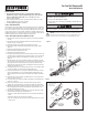
4. Disconnect the master link from the trolley threaded shaft and belt; discard
(Figure 1).
5. Remove the spring/nut from the trolley and discard.
6. Remove idler pulley assembly and set aside.
7. Remove the belt assembly and discard.
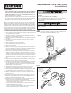
8. Push the trolley back toward the opener. Disconnect the front rail and second rail
sections by using a screwdriver tip to pry up the outer tab on each side of the rail,
then slide it off the existing rail assembly. Discard the front and second rails
(Figure 2).
9. Align the new front and center rails with the existing rail assembly, keeping the
cut out “window” at the front (header) end. Be sure to keep rails right side up: the
idler pulley bolt hole above the window is larger on top of the rail than on the
bottom. Slide the new center rail onto the assembly, then add the front rail. Tabs
along the side will lock into place.
10. As a temporary stop, insert a screwdriver into the hole 10" (25 cm) from the front
end of the rail (Figure 1). Slide the trolley assembly to this point.
11. Lay the new belt beside the rail. Grasp the end with the hooked trolley connector
and pass approximately 12" (30 cm) of belt through the window. Keeping the
ribbed side toward the rail, and allow it to hang while you complete the next two
steps.
12. Replace the idler pulley, lock washer and nut. Rotate it to be sure it spins freely.
Grease the center if necessary.
13. Locate the rail tab. Use a flathead screwdriver and lift the rail tab until the tab is
vertical (90°) (Figure 2).
14. Pull the belt around the idler pulley and hook the trolley connector into the
retaining slot on the trolley (Figure 1). The ribbed side must contact the pulley.
15. With the trolley against the screwdriver, dispense the remainder of the belt along
the rail length toward the motor unit and around the sprocket (Figure 1). The
sprocket teeth must engage the belt.
16. Check to make sure the belt is not twisted, then connect it to the flat end of the
trolley threaded shaft with the master link (Figure 1):
• Push pins of master link bar through holes in end of belt and trolley threaded
shaft.
• Push master link cap over pins and past pin notches.
• Slide clip-on spring over cap and onto pin notches until both pins are securely
locked in place.
Figure 1
Figure 2
To remove rail pry both
end tabs of front
rail slightly outward
Idler Bolt hole
(KEEP LARGER
ONE ON TOP)
NEW
FRONT RAIL
CORRECT
INCORRECT
Rail Tab
Rail Tab
Master
Link
Trolley
Connector
Retaining
Slot
Threaded
Shaft
Front Rail
Section
Master
Link
Idler Pulley
Retaining
Slot
Trolley
Connector
WARNING: This product can expose you to chemicals including lead, which
are known to the State of California to cause cancer or birth defects or other
reproductive harm. For more information go to www.P65Warnings.ca.gov.
REFER TO GARAGE DOOR OPENER MANUAL FOR DETAILED INSTALLATION,
ADJUSTMENTS, AND SAFETY INFORMATION.
To prevent possible SERIOUS INJURY or DEATH:
• Disconnect ALL electric and battery power BEFORE performing ANY service
or maintenance.
The garage door MUST be in the fully closed position during installation.