Owner’s Manual/Manual Del Propietario GARAGE DOOR OPENER Abridor de puerta de cochera MODEL/MODELO 200.57933 Read and follow all safety rules and operating instructions before first use of this product. Fasten the manual near the garage door after installation. Periodic checks of the opener are required to ensure safe operation. DO NOT install on a one-piece door.
Table of Contents Introduction Symbols and Icons Inventory Preparation / Tools Required 2 3 4 Assembly Rail and Trolley Assembly Installing the Cable and Chain Important Installation Instructions Mounting Header Bracket 5 6 7 8 Installation Attaching Rail to Header Bracket and Mounting Door Bracket Mounting Opener to Ceiling Attaching Door Arms Installing Light and Emergency Release Handle 9 10 11 12 Wiring Wiring Instructions Connecting Photo Eye Safety System Connecting Push Button Connecting Power
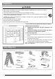
Inventory Rail — Header Segment Rail — Middle Segments x3 Opener Unit + Light Lens Cover Photo Eye Safety System Rail — End Segment with Trolley Stop Bolt OPTIONAL OPTIONAL x2 Screw #6 x 1” x2 Drywall Anchor 1-Button Remote Sprocket Cover Emergency Release Handle + Rope Literature + Safety Labels Push Button Trolley Trolley Shaft and Cable 3-Button Mini Remote* Wireless Keyless Entry Keypad* Header Bracket Chain Hanging Brackets Door Bracket Pulley Door Arms *See Accessories in Repair P
Preparation ! WARNING To prevent SERIOUS INJURY or DEATH: - Before beginning installation of the opener please complete the following test to ensure that your door is balanced and in good working condition. - A poorly balanced door can cause serious injury and damage to the opener. - Always have a qualified garage door service technician make any required adjustments and/or repairs to your door before proceeding with installation.
Rail and Trolley Assembly Fig.1 ! CAUTION - DO NOT connect power until instructed. - To prevent INJURY, keep hands and fingers away from joints and possible sharp edges. - Wear gloves when installing chain and cable. Rail — End Segment (tapered) with Trolley Stop Bolt Rail Bracket Rail — Middle Segments (tapered) x 3 Trolley direction (Top View) Opener Rail — Header Segment When connecting the rails ensure they are securely connected as shown above.
Installing Cable and Chain ! WARNING To prevent SERIOUS INJURY: - DO NOT connect power until instructed. - Keep hands and fingers clear from sprocket during operation. - Wear gloves when installing chain and cable. - Keep hands and fingers away from joints and possible sharp edges. Cable Rail Bracket Sprocket Chain To Install Chain 1. Pull the remaining chain along the rail toward the opener. 2. A segment of chain marked in RED will be seen.
Important Installation Instructions IMPORTANT INSTALLATION INSTRUCTIONS ! WARNING To reduce the risk of severe injury or death: 1. 2. 3. 4. 5. 6. 7. READ AND FOLLOW ALL INSTALLATION INSTRUCTIONS. Install only on a properly balanced garage door. An improperly balanced door has the potential to inflict severe injury. Have a qualified service person make repairs to cables, spring assemblies, and other hardware before installing the opener.
Mounting Header Bracket ! WARNING To prevent SERIOUS INJURY: - DO NOT connect power until instructed. - The header bracket MUST be SECURELY fastened to the structural support on the mounting wall or ceiling, otherwise the door may not reverse when required. DO NOT install the header bracket over drywall. - Concrete anchors MUST be used when mounting the header bracket into masonry. - NEVER try to loosen, move or adjust garage door springs, cables, pulleys, brackets, or hardware.
Attaching Rail to Header Bracket and Mounting Door Bracket ! CAUTION To prevent SERIOUS INJURY: - DO NOT connect power until instructed. - REINFORCEMENT is recommended for fiberglass, aluminum or lightweight steel garage doors BEFORE installing the door bracket. Contact your door manufacturer for reinforcement options. To Attach the Opener to the Header Bracket 1. As shown in Fig.1, use the packaging carton as temporary support for the opener. Place the opener on carton to prevent damage. 2.
Mounting Opener to Ceiling ! WARNING To prevent SERIOUS INJURY or DEATH: - DO NOT connect power until instructed. - Install the opener at least 7 feet (2.13m) above the floor. - Fasten the opener SECURELY to STRUCTURAL SUPPORTS of the garage to prevent falling. - If installing brackets to masonry, concrete anchors (not provided) MUST be used. To Mount the Opener to Ceiling The three most common installation options are shown in Fig.1-3. Fig.
Attaching Door Arms ! WARNING To prevent SERIOUS INJURY: - DO NOT connect power until instructed. - Keep hands and fingers away from the sprocket during operation. - Wear gloves when installing chain and cable. - Keep hands and fingers away from joints and possible sharp edges. Min. 8” (20cm) NOTE: The trolley must be a minimum of 8” (20cm) away from the pulley. 1 Straight Door Arm To Connect Door Arm Follow the steps shown in Fig. 1 1.
Installing Light and Emergency Release Handle ! WARNING To prevent SERIOUS INJURY or DEATH from electrocution: - Disconnect power cord before installing/replacing light bulb. To prevent possible OVERHEATING or damage to opener: - Use ONLY A19 (E26) incandescent bulbs* (100W max.). - DO NOT use short neck or specialty light bulbs. - DO NOT use halogen bulbs. * CFL or LED light bulbs will work but may interfere with hand-held remotes. To install the light: 1.
Wiring Instructions ! WARNING To prevent SERIOUS INJURY or DEATH from electrocution: - Power MUST NOT be connected until instructed. - NO exposed part of the wire should be visible outside of the terminal for proper connection. * VERY IMPORTANT! * In the following section, the photo eye safety system and push button will be connected to the opener. Please read and understand the wiring instructions before connecting wires. Wire from accessories Remove and discard pre-cut skin 1.
Connecting Photo Eye Safety System ! WARNING To prevent SERIOUS INJURY or DEATH from electrocution: - Power MUST NOT be connected BEFORE photo eye safety system is connected and aligned. - The opener will not operate until the photo eye safety system is properly connected and aligned. - Install the photo eyes NO higher than 6” (15cm) above the floor. No part of garage door or other objects should obstruct the photo eye safety system during door-closing.
Connecting Push Button ! WARNING To prevent SERIOUS INJURY or DEATH from electrocution: - Power MUST NOT be connected until instructed. To prevent SERIOUS INJURY or DEATH from using the push button and a closing door: - Install the push button within sight of the door at a minimum height of 5 feet (1.5m) above the floor. Make sure it is out of the reach of children and moving parts of door and hardware. - NEVER permit children to access the push button or remote controls.
Connecting Power ! WARNING To prevent SERIOUS INJURY or DEATH from electrocution or fire: - Power MUST be DISCONNECTED BEFORE proceeding with permanent wiring procedures. - Garage door opener installation and wiring MUST be in compliance with all local electrical and building codes. Make sure the opener is ALWAYS grounded. - NEVER use an extension cord, 2-wire adapter or modify the power plug in any way to make it fit the outlet. DO NOT OPERATE OPENER AT THIS TIME.
Travel Limit Adjustment ! WARNING To prevent SERIOUS INJURY or DEATH from improper force adjustment: - Improper adjustment of travel limits will cause operation of safety reversal mechanism. - If travel limit adjustment is made, force adjustment may also needed. - After ANY adjustments, the safety reverse test MUST be performed to ensure the door reverses on contact with a 1-1/2” thick object (2x4 laid flat).
Force Adjustment ! WARNING To prevent SERIOUS INJURY or DEATH from improper force adjustment: - DO NOT adjust force to compensate for binding or sticking of the garage door. Call a qualified garage door service technician to make necessary adjustments in case of binding. - DO NOT increase the force beyond minimum force required for closing the door. Too much force will cause improper operation of safety reversal mechanism.
Final Adjustments and Testing ! WARNING To prevent SERIOUS INJURY or DEATH from a closing garage door: - The Safety Reversal Test MUST be conducted ONCE A MONTH. - NO ONE should cross the path of moving door during operation and/or testing. - If either force or travel limit adjustment is made, the other adjustment may also needed. - After ANY adjustments to the door system, the Safety Reverse Test MUST be performed to ensure the door reverses on contact with a 1-1/2” thick (2x4 laid flat) object.
Programming 1– Button Remote ! WARNING To prevent SERIOUS INJURY or DEATH: - Keep remote and battery out of reach of children. - NEVER permit children to access the wall panel nor remotes. - Operate the door ONLY when it is properly adjusted, and there are no obstructions present. - ALWAYS keep a moving door in sight until completely closed. NEVER cross the path of a moving door.
Programming Wireless Keyless Entry Keypad * To purchase a wireless keyless entry keypad, visit a Craftsman outlet, call 1-888-331-4569, or go online to www.craftsman. com ! WARNING To prevent SERIOUS INJURY or DEATH: - Keep remote and battery out of reach of children. - NEVER permit children to access the wall panel, push button nor remotes. - Operate door only when it is adjusted properly with no obstructions to door travel and is in clear sight.
Important Safety Instructions IMPORTANT SAFETY INSTRUCTIONS ! WARNING To reduce the risk of severe injury or death: 1. 2. 3. 4. 5. 6. 7. READ AND FOLLOW ALL INSTRUCTIONS. Never let children operate or play with door controls. Keep the remote control away from children. Always keep the moving door in sight and away from people and objects until it is completely closed. NO ONE SHOULD CROSS THE PATH OF THE MOVING DOOR. NEVER GO UNDER A STOPPED, PARTIALLY OPEN DOOR. Test door opener monthly.
Operating the Opener ! WARNING To prevent SERIOUS INJURY or DEATH: - READ AND FOLLOW ALL INSTRUCTIONS AND WARNINGS IN THE OWNER’S MANUAL AND LABELS - Keep remote and battery out of reach of children. - NEVER permit children to access the push button or remotes. - Operate the door ONLY when it is properly adjusted, and there are no obstructions and is in clear sight. - ALWAYS keep a moving door in sight until completely closed. NEVER cross the path of a moving door.
Door Status vs.
Maintenance Schedule Once a month Maintenance Door balance test, refer to page 4. Safety reverse test, refer to page 19. Twice a year Check chain tension ( refer to page 6 for adjustment if necessary). Once a year - Limit and force adjustment may be necessary due to weather conditions. Refer to pages 17-18 for adjustment. Conduct safety reverse test after ANY adjustments. - Lubricate door rollers, bearings and hinges.
Repair Parts To purchase repair parts, call 1-888-331-4569. Rail Assembly Parts 1 Item Part No. 1 RP-001 Rail—Header Segment 2 RP-002 Rail—Middle Segments 3 RP-003 Rail—End Segment with Stop Bolt 2 3 4 4 5 6 GUT-840 Pulley 5 RP-004 Trolley 6 RP-005 Trolley Shaft and Cable 7 7 Name / Description GUT-410 Master Link Set 8 RP-006 Item Part No.
Opener Assembly Parts 1 5 2 4 3 10 8 9 6 Limit System Assembly 11 12 7 Open limit Contact 13 Green Screw Blue Green Gear Center limit Contact Close limit Contact 14 Item Part No.
CRAFTSMAN WARRANTY 90-DAY IN-HOME LIMITED WARRANTY FOR 90 DAYS from the date of sale this product is warranted against defects in material or workmanship. With proof of purchase a defective product will be repaired free of charge. LIMITED WARRANTY ON PARTS FROM THE 91st DAY THROUGH 1 YEAR from the date of sale this product is warranted against defective parts. With proof of purchase a new part will be furnished to replace a defective one free of charge.
Tabla de Contenidos Introducción Símbolos e Íconos Inventorio Preparación / Prueba de Balance de la Puerta Herramientas Requeridas 29 30 31 31 Montaje Montaje del Riel y Carro Instalación de la cabel y cadena Instrucciones Importantes de Instalación Montaje del Soporte Cabecero 32 33 34 35 Instalación Colocación del Riel en el Soporte Cabecero Montaje del Soporte de la Puerta Montaje del Abre-puerta al Techo Fijación de los Brazos de la Puerta Instalación de la Luz y la Manija de Desconexión de Emergenc
Inventario Riel — Segmento de Cabecera Riel — Segmentos Intermedios x3 Abre-puertas de garage y mica Riel — Segmento Final con perno de Parada del Carro Fotoelectrico OPCIONAL OPCIONAL x2 Tornillo #6 x 1” x2 Cubierta de portacadena 1-Botón Remoto Para panel Tarugo de yeso Botón de Control Teclado Acceso Sin Llave* Manilla de Emergencia + Cuerda Carro Literatura + Etiquetas de seguridad Varilla Eje del carro y cable Soporte de cabecera Cadena and Soportes Colgantes 3-Mini Botón Remoto* So
Preparación ! ADVERTENCIA Para evitar LESIONES GRAVES o la MUERTE: - Antes de iniciar la instalación de la unidad, por favor, complete la siguiente prueba para asegurar que su puerta esté balanceada y en buenas condiciones de funcionamiento. - Una puerta mal balanceada puede causar lesiones graves y daños en la unidad abre-puertas. - Siempre haga que un técnico de servicio calificado en puertas de garaje realice los ajustes o las reparaciones necesarias en su puerta antes de proceder con la instalación.
Montaje del Reil y Carro ! Riel — Segmento final (cónico) con perno limitador del carro PRECAUCIÓN - NO conecte la electricidad sino hasta que se le indique. - Para evitar LESIONES, mantenga las manos y los dedos lejos de las junturas y de los posibles bordes filosos. Soporte del riel - Utilice guantes al instalar la cadena y el cable.
Instación del cable y la cadena ! ADVERTENCIA Para evitar LESIONES GRAVES: - NO conecte la electricidad sino hasta que se le indique. - Mantenga las manos y los dedos lejos de la rueda dentada durante la operación. - Utilice guantes cuando instale la cadena y el cable. - Mantenga las manos y los dedos lejos de las junturas y de los posibles bordes filosos. Cable Soporte del riel Rueda dentada Cadena Para instalar la cadena 1. Tire el resto de la cadena a lo largo del riel hacia el abre-puerta. 2.
Instrucciones Importantes de Instalación Instrucciones Importantes de Instalación ! ADVERTENCIA Para reducir el riesgo de lesiones graves o la muerte: 1. LEA Y RESPETE TODAS LAS ADVERTENCIAS Y LAS INSTRUCCIONES DE INSTALACIÓN. 2. Instale el abre-puerta solamente en puertas de cochera que estén bien equilibrado y lubricados. Si la puerta no está debidamente equilibrada es posible que no retrocede cuando así se requiera y podría ocasionar una lesión grave o incluso la muerte.
Montaje del Soporte Cabecero ! ADVERTENCIA Para evitar LESIONES GRAVES: - NO conecte la electricidad sino hasta que se le indique. - El soporte del travesaño DEBE estar BIEN sujeto al soporte estructural sobre la pared o en el techo de montaje, de lo contrario, la puerta no podrá retroceder cuando se requiera. NO instale el soporte del travesaño sobre drywall. - DEBEN utilizarse anclajes de concreto cuando el montaje del soporte del travesaño es en mampostería.
Colocación del Riel en el Soporte Cabecero y Montaje del Soporte de la Puerta ! ADVERTENCIA Para evitar LESIONES GRAVES: - NO conecte la electricidad sino hasta que se le indique. - Se recomienda REFUERZO para las puertas de garaje de fibra de vidrio, aluminio o acero ligero ANTES de instalar el soporte de la puerta. Póngase en contacto con el fabricante de su puerta para conocer las opciones de refuerzo. Unir el Abre-puerta con el Soporte Cabecero 1.
Montaje del Abre-puerta al Techo ! ADVERTENCIA Para evitar LESIONES GRAVES o la MUERTE: - NO conecte la electricidad sino hasta que se le indique. - Instale la unidad abre-puertas por lo menos a 7 pies (2,13 m) por encima del piso. - Ajuste BIEN la unidad a los SOPORTES ESTRUCTURALES del garaje para evitar que se caiga. - Si los soportes se instalan en mampostería, SE DEBEN utilizar anclajes de concreto (no incluidos).
Fijación de los Brazos de la Puerta ! ADVERTENCIA Para evitar LESIONES GRAVES: - NO conecte la electricidad sino hasta que se le indique. - Mantenga las manos y los dedos lejos de la rueda dentada durante la operación. - Utilice guantes cuando instale la cadena y el cable. - Mantenga las manos y los dedos lejos de las junturas y de los posibles bordes filosos. Min. 8” (20cm) NOTA: El brazo recto de la puerta debe ser instalado verticalmente a la puerta cuando la puerta está en la posición cerrada.
Instalación de la Luz y la Manija de Desconexión de Emergencia ! ADVERTENCIA Para prevenir LESIONES GRAVES o MUERTE por electrocución: - Desconecte el cable de alimentación antes de instalar / reemplazar la bombilla. Para evitar un posibles SOBRECALENTAMIENTO o daños al abridor: - Utilice SOLAMENTE bombillas incandescentes A19 (E26) * (100W máx.). - NO utilice bombillas cortas o de especialidad. - NO utilice bombillas halógenas.
Instrucciones de Cableado ! ADVERTENCIA Para prevenir LESIONES GRAVES o MUERTE por electrocución: - La energía NO DEBE conectarse hasta que se le indique. - Ninguna parte expuesta del cable debe ser visible fuera del terminal para la conexión correcta. * MUY IMPORTANTE! * En la siguiente sección, el Sistema de Seguridad de Sensor Óptic y el Botón Pulsador serán conectados al Abre-puerta. Por favor lea y entienda las intrucciones de cableado antes de conectar los cables. Cable desde los accesorios 1.
Conexión del Sistema de Seguridad de Sensor Óptico ! ADVERTENCIA Para evitar LESIONES GRAVES o la MUERTE por electrocución: - NO SE DEBE conectar la electricidad ANTES de que esté conectado y alineado el sistema de sensor fotoeléctrico de seguridad. - La unidad no funcionará sino hasta que el sistema de sensor fotoeléctrico de seguridad esté instalado y alineado de manera apropiada. - Instale el sensor fotoeléctrico NO más alto de 6” (15 cm.) por encima del piso.
Conexión del Botón de Control ! ADVERTENCIA Para evitar LESIONES GRAVES o la MUERTE por electrocución: - NO SE DEBE conectar la electricidad sino hasta que se le indique. Para evitar LESIONES GRAVES o la MUERTE por utilizar el botón de oprimir cuando la puerta se está cerrando: - Instale el botón de oprimir a la vista de la puerta a una altura mínima de 5 pies (1,5 m) por encima del piso. Asegúrese de que esté fuera del alcance de los niños y lejos de las partes móviles de las puertas y el equipo.
Conexión de la Fuente de Alimentación ! ADVERTENCIA Para evitar LESIONES GRAVES o la MUERTE por electrocución o fuego: - La electricidad SE DEBE DESCONECTAR ANTES de proceder con los procedimientos de cableado permanente. - La instalación de la unidad abre-puertas de la puerta de garaje y el cableado DEBEN cumplir con todos los códigos eléctricos y de construcción locales. Asegúrese de que la unidad abre-puertas esté SIEMPRE conectada a tierra.
Ajuste del Límite de Recorrido ! ADVERTENCIA - Para prevenir LESIONES GRAVES o MUERTE debido a un ajuste de fuerza inadecuado: - Un ajuste incorrecto de los límites de recorrido causará el funcionamiento del mecanismo de inversión de seguridad. - Si se realiza el ajuste del límite de recorrido, también puede ser necesario ajustar la fuerza.
Ajuste de Fuerza ! ADVERTENCIA Para evitar LESIONES GRAVES o la MUERTE por el ajuste inapropiado de la fuerza: - NO ajuste la fuerza para compensar el que la puerta del garaje se atora o pega. Llame a un técnico de servicio calificado para puertas de garaje para realizar los ajustes necesarios en caso de atoramiento. - No aumente la fuerza más allá de la fuerza mínima requerida para el cierre de la puerta. Demasiada fuerza causará un inapropiado funcionamiento del mecanismo de seguridad de reversa.
Ajuste Final y Prueba ! ADVERTENCIA Para evitar LESIONES GRAVES o la MUERTE por una puerta de garaje que se esté cerrando: - La prueba de seguridad de reversa DEBE realizarse UNA VEZ AL MES. - NADIE debe cruzar el paso de la puerta en movimiento durante su funcionamiento o puesta a prueba. - Si se hace el ajuste de la fuerza o el del límite del recorrido, es posible que también se necesite el otro ajuste.
Programación del Control Remoto ! ADVERTENCIA Para evitar LESIONES GRAVES o la MUERTE: - Mantenga el control remoto y la pila fuera del alcance de los niños. - NUNCA permita que los niños accedan al botón de oprimir o a los controles remotos. - Haga funcionar la puerta SÓLO cuando esté ajustada de manera apropiada, y no hay obstrucciones presentes. - SIEMPRE mantenga vigilada una puerta en movimiento hasta que cierre por completo. NUNCA cruce el espacio de una puerta en movimiento.
Programación del Teclado de Acceso sin Llave * Para comprar un teclado sin llave, visite una tienda de Craftsman, llame al 1-888-331-4569, o visite www.craftsman.com ! ADVERTENCIA Para prevenir LESIONES GRAVES o MUERTE: - Mantenga el transmisor y la batería fuera del alcance de los niños. - NUNCA permita que los niños accedan al panel de pared, el pulsador ni a los transmisores remotos. - Opere la puerta SOLO cuando esté ajustada adecuadamente, sin obstrucciones en el recorrido de la puerta y despejada.
Instrucciones Importantes de Seguridad INSTRUCCIONES IMPORTANTES DE SEGURIDAD ADVERTENCIA Para reducir el riesgo de lesiones graves o lamuerte: ! 1. LEA Y RESPETE TODAS LAS ADVERTENCIAS Y LAS INSTRUCCIONES DE INSTALACIÓN. 2. Siempre guarde los controles remotos lejos del alcance de los niños. Nunca permita que los niños hagan funcionar o jueguen con el botón del control del abre-puerta de la cochera o con los controles remotos. 3.
Operación del Abridor ! ADVERTENCIA Para evitar LESIONES GRAVES o la MUERTE: - LEA Y SIGA TODAS LAS INSTRUCCIONES Y LAS ADVERTENCIAS EN EL MANUAL DEL PROPIETARIO Y LAS ETIQUETAS. - Mantenga el control remoto y la pila fuera del alcance de los niños. - NUNCA permita que los niños accedan al botón de oprimir o a los controles remotos. - Haga funcionar la puerta SÓLO cuando esté ajustada de manera apropiada, y cuando no hay obstrucciones y esté a la vista.
Estado de la Puerta vs.
Mantenimiento Programación Una vez al mes Mantenimiento Prueba de balance de la puerta, consulte la página 31. Prueba de seguridad de marcha atrás, consulte la página 46. Dos veces al año Una vez al año Verificación de la tensión de la cadena (consulte la página 32 para ajustes si es necesario). - Ajustes de límite de desplazamiento y fuerza pueden ser necesarios debido a las condiciones climáticas. Consulte las páginas 44-45 para ajustes.
Piezas de Recambio Para comprar piezas de recambio, llame al 1-888-331-4569 Piezas del Montaje del Riel 1 Item Part No. 1 RP-001 Riel - Segmento de la cabecera 2 RP-002 Riel - Segmento del medio 3 RP-003 Riel - Segmento final (cónico) con perno limitador del carro 2 3 4 5 4 6 8 GUT-840 Ménsula 5 RP-004 Carro 6 RP-005 Varilla de carro y cable 7 7 Name / Description GUT-410 Juego de enlace maestro 8 RP-006 Cadena Item Part No.
Piezas del Montaje del Abridor 1 5 2 4 3 10 8 9 6 Montaje del Sistema Límite 11 12 7 Contacto límite apertura 13 Tornillo Verde Azul Verde Engranaje Contacto Límite de Cierre 14 Contacto Límite de Cierre Ítem Pieza No.
GARANTÍA CRAFTSMAN GARANTÍA LIMITADA DE 90 DÍAS EN EL HOGAR POR 90 DÍAS a partir de la fecha de venta este producto está garantizado contra defectos de material o mano de obra. Con la prueba de compra, un producto defectuoso será reparado gratuitamente. GARANTÍA LIMITADA EN LAS PIEZAS A PARTIR DEL 91º DÍA A 1 AÑO de la fecha de venta este producto está garantizado contra piezas defectuosas. Con la prueba de compra, será suministrada una pieza nueva para reemplazar una defectuosa de forma gratuita.