trend routing technology ROUTER TABLE for the Craftsman Instruction Manual Model Numbers: CRT/A CRT/B CRT/C CRT/D CRT/E CRT/X Trend Machinery & Cutting Tools Ltd. Penfold Works Imperial Way Watford Hertfordshire WD2 4YF England Sales: _________________ 01923 249911 Technical Enquiries: ____ 01923 224681 Fax: ___________________ 01923 236879 Email: _______ mailserver@trend.co.uk WWW: ____ http://www.trendm.co.
Router Table for thefrom Craftsman Routing Products the UK Leader Dear Customer Thank you for purchasing the Trend Router Table for the Craftsman. We hope you enjoy many years of creative and productive use of this product. Trend welcomes comments on this and all our products in our aim to develop and improve what we do to meet the needs of you, the customer. Please contact our Technical Department in the first instance if you have any comments or queries.
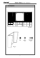
Router Table for the Craftsman INTRODUCTION CONTENTS ________________________ Page This Router Table is designed for the woodworking Craftsman and especially those new to the art of routing. Contents, Introduction, Tools Required _______ 1 Safety Precautions, Specs, Cutter Care, Advice 3 Assembly Instructions The Router Table has the necessary features to extend the versatility of most portable routers when profiling, edging, rebating and jointing. A.
Router Table for the Craftsman SAFETY PRECAUTIONS CUTTER CARE 1. Always switch off the power and unplug the router when changing cutters or when making adjustments. 1. Do not drop cutters or knock them against hard objects. 2. Always wear protective goggles when routing. 2. 3. Wear sound protective ear muffs when routing for long periods of time. 4. Cutters should be kept clean. Resin build-up should be removed at regular intervals with a wire brush.
Router Table for the Craftsman Table Components Table Surface x1 Nuts x 12 Table Leg x2 -4- Star Washers x 12 Dome Headed Screws x 12
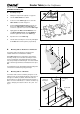
Router Table for the Craftsman ASSEMBLY INSTRUCTIONS Leg A. Assembly of Legs 1. Identify the components required, see opposite 2. Turn the Table Surface face down. 3. Locate one of the Table Legs at one end of the Table Surface as shown in figure A. 4. Insert the Dome Headed Screws through the six holes in the Table Surface and Table Leg. Six screws are required for each of the two Table Legs. 5. Lightly tighten the Nuts and Star Washers on to each Dome Headed Screw.
Router Table for the Craftsman CRT/PLATE A (inc.
Router Table for the Craftsman CRT/PLATE D (inc. Fixing Pack) supplied with Router Table CRT/D Fixing Pack Router Models M4 x 12mm (4) J2,K2 Holes Fixings Following models will fit insert plate J2,K2 K1 Makita 3612BR J1 M5 x 16 J2 M4 x 12 K1 K2 M5 x 16 M4 x 12 M5 x 16mm (2) Makita 3612, Makita 3612C J1 J1 J2,K2 K1 J2,K2 Threaded hole for Lead-On pin CRT/PLATE E (inc.
Router Table for the Craftsman D. base. The fixing screws can then be used to secure. The use of a gasket serves two purposes, firstly it allows for secure fixing of the router, and secondly, due to the small aperture in the router it allows the tabs of the insert rings to fit tightly to the plate. Enlarging the aperture in the base of the router is also advised if large diameter tooling is to be used. Identification of Mounting Holes and Screws See previous page to: 1.
Router Table for the Craftsman 10. router or any webbings in the casting of the router base. A slight turning of the plate may be required to miss such obstructions. (i) Note If you do not have the necessary equipment to carry out operations 7 and 8, then a local engineering shop will be able to carry them out accurately.
Router Table for the Craftsman H. Fitting Insert Plate to Table Surface 1. Identify the components required, see below. Nylock Nut with Nylon ring facing up Insert Plate Adjustable Bolts x4 Insert Plate Retaining Bolts x4 Insert plate adjustment bolt Nylock Nuts x 8 Fig. G.1 2. Assemble the four Insert Plate Adjustment Bolts and the four Nylock Nuts to table as shown in fig. G1. After a few turns some resistance will be felt as the screws are gripped by the Nylock Nuts.
Router Table for the Craftsman J. Selecting & Fitting Insert Plate Rings The Insert Plate Rings are designed to support the workpiece around the cutter to avoid small timber sections tipping or flexing when being machined. 1. First separate all Insert Plate Rings from each other using a sharp knife and trim off all flashes, see fig. J.1. Selecting the correct size of Ring 2.
Router Table for the Craftsman Tenon Push Block Components Clamp Rod x 1 Spring Washer x1 Nut x 1 Washer x 1 Wing Nut x 1 Clamp Plate x 1 Push Block x 1 Safety Dust Guard Components Pivot Pin x 1 Push Nuts x 2 Dust Guard x 1 (not shown actual size) -12-
Router Table for the Craftsman L. Assembly of Tenon Push Block 1. Identify the components required, see opposite. 2. Screw the smaller threaded end of the Clamp Rod into threaded hole in Clamp Plate until the plate bottoms on it’s shoulder (make sure clamp is oriented such that letter 'C' is facing outwards as shown in fig. L.1) and tightly secure Clamp Plate to Clamp Rod with a 11mm AF spanner. 3.
Router Table for the Craftsman Back Fence Components Back Fence x 1 Workpiece Support x 1 Medium Size Knob x 1 Large Size Knob x 2 Washer x 1 Washer x 2 -14- Workpiece Support Adjustment Bolt x 1 Back Fence Fixing Bolts x 2
Router Table for the Craftsman N. Assembly of Back Fence 1. Identify the components required, see opposite. 2. Slide Workpiece Support through rectangular opening in the aperture provided in the Back Fence. The V-guide on the Back Fence should engage in the V-guide on the under side of Workpiece Support, see fig. N and page 21 for use. Knob (medium size) 3. 4.
Router Table for the Craftsman Mitre Fence Components Mitre Fence Head x 1 Small Size Knob x 1 Bolt x 1 Washer x 1 Pointer x 1 Securing Bolt x 1 Nut x 1 Mitre Bar x 1 -16-
Router Table for the Craftsman Q. Assembly of Mitre Fence 1. Identify the components required, see opposite. 2. Insert the pin of the Mitre Fence Head into the Mitre Bar. 3. Insert the Securing Bolt and fit the Flat Washer and Securing Knob (small size). 4. Remove any flash on the plastic pointer with a sharp knife. Knob Flat washer Mitre fence head Knob 5. Pointer Mitre bar Position the pointer as shown in fig. Q.1 and insert the bolt, then fit the nut. Securing bolt Hex nut fig. Q.
Router Table for the Craftsman OPTIONAL ACCESSORIES swivel freely when fitted to the hose. R. Dust Extraction Equipment Assembly of Hose Adaptor The Back Fence is provided with an extraction point for fitting to suitable dust extractors. The internal hole diameter is 57mm (2 1/4"). Suitable fittings with 57mm outside diameter are available with most extractor units. 1. Slide Adaptor Clip onto end of the Extraction Hose CRT/4 with tabs facing outwards. 2.
Router Table for the Craftsman T. 6. Assembly of Spring Pressure Clamps The Optional Spring Pressure Clamps can be mounted to the Back Fence. When adjusted to suit the width and thickness of the material, it ensures the material is held down onto the surface to obtain accurate machining of the workpiece. The Back Fence is pre-drilled to accept both Spring Pressure Clamps. 1. Remove Back Fence from Table Surface 2. Insert Vertical Pillar Bolt through the underside of the Back Fence. 3.
Router Table for the Craftsman U. Adjustment Assembly of Profiling Top Guard The use of the optional accessory, Profiling Top Guard is highly recommended to safely carry out the profiling of workpieces with a bearing guided cutter. It will prevent the operator's fingers inadvertantly contacting the cutter. Fit the Bolt, Star Washer, Spring Washer and Nut in the sequence as indicated below. 1. 2. Tighten nut securely with a 8mm spanner. 3. Fit Plate, Washer and Wing Nut. 4.
Router Table for the Craftsman OPERATION V. Edging and Profiling using the Back Fence The router table has many advantages when profiling and edging operations are to be carried out especially on narrow workpieces. A Fine Height Adjuster fitted to the router will make adjustment of the height far easier and hence is highly recommended. Craft Range Ref. C020 Craft Range Ref. C072 Craft Range Ref. C040 Craft Range Ref. C112 Craft Range Ref.
Router Table for the Craftsman W. Using Router Table for Grooving The router table can be used for operations away from the edge of the workpiece such as grooving, fluting, veining, etc. Always unplug the router before making any setting, adjustments, or changing bits. When routing, always feed against the rotation of the cutter. Feed workpiece in the direction of arrow in fig. W.2. For maximum accuracy, one edge of your workpiece (edge sliding against the fence) must be true and straight.
Router Table for the Craftsman Craft Range Cutter Ref. C116 Guard Template 6mm Lead-on Pin Table Surface Insert Plate Insert Ring fig. Y.1 Craft Range Cutter Ref. C078 Guard 6mm Table Surface Lead-on Pin Insert Plate fig. Y.
Router Table for the Craftsman Y. Using The Profiling Top Guard b. Gradually swing workpiece towards cutter until template engages the guide bearing. Example c. Feed workpiece against the rotation of the cutter whilst swinging the workpiece away from the Lead-On Pin. At this point the guided bearing is acting as the guide. Progressively feed the workpiece anti-clockwise around the shape of the template ensuring that the guide bearing always stays in contact with the template.
Router Table for the Craftsman Moulding the Shield The following precautions should be made to avoid a potentially dangerous situation: A suitable bearing guided cutter should be chosen to mould the shield. 1. Remove plug from mains. 2. Fit chosen moulding cutter. 3. Adjust height of cutter to achieve shape required. If the full edge of the workpiece is to be machined leave the template attached to the workpiece so as to provide a guide for the bearing.
Router Table for the Craftsman Z. End Cutting with the Tenon Push Block Typical width of tenon is 1/3 of thickness of material The Push Block facility is ideal for producing tenons and sliding dovetails. Shoulder The retractable dust guard cannot be used when carrying our push block operations. Therefore extra care must be taken to ensure that hands are kept well clear of the cutter. A Face Side Face Edge Ensure that the workpiece is true and the end is square and smooth. 1.
Router Table for the Craftsman Spare Parts for Router Table Model CRT/A, CRT/B, CRT/C and CRT/X 79 38 40 42 12 2 3 2 3 3 4 3 46 3 3 3 12 3 to socket for plug of router 43 to plug at mains supply 47 2 4 4 11 15 44 12 3 2 48 3 9 10 3 3 52 3 9 45 12 8 7 6 3 3 51 16 3 3 3 5 3 53 75 12 77 2 4 27 26 23 76 12 22 36 29 21 4 78 54 3 3 3 3 9 3 39 1 18 39 41 5 30 3 32 28 31 3 25 19 30 3 25 14 34 17 20 2 33 4 24 -28- 4
Router Table for the Craftsman Instruction Manual 73 80 R tre ro ut in nd e g t ch no lo gy Spare Parts for Optional Accessories Profiling Top Guard Spring Pressure Clamp 72 67 62 68 74 66 70 65 61 60 64 59 58 63 57 71 56 55 KEY PART NO.
Router Table for the Craftsman 21mm 77mm 77mm 4 holes for M5 M/C screws 21mm 77mm Position of Router Handle 77mm APPENDIX 21mm C FRONT OF CRT TABLE Plan for HITACHI TR12 Router Position of Router Handle C -30- 21mm
C Plan for RYOBI R600, RE600 Routers 59mm -31- C 37mm Position of Router Handle 40mm Position of Router Handle 44mm 54mm * The plate for the CRT/B table is pre-drilled to accept the two central fixings M5 M/C screw FRONT OF CRT TABLE 4 holes for M4 M/C screws Router Table for the Craftsman 44mm 2 holes for M5 M/C screws*
Router Table for the Craftsman Position of Router Handle 68mm C 59.25mm FRONT OF CRT TABLE 34.5mm C Position of Router Handle 3 holes for No.
Position of plate 65° C 2 off 6mm dia. through holes required to be drilled into base of router.
Router Table for the Craftsman approx. 100mm 115mm 60mm Ø approx. 145mm 14.5mm MATERIAL MIN. 6.35mm (1/4") THICK.
approx. 100mm Plan showing gasket required for Bosch POF52, 400A, 500A & 600 ACE -35- MATERIAL MIN. 3.2mm (1/8") THICK approx.