Operator's Manual ® CTX Model No. 107.250050 Yard Tractor (22 Gross HP Briggs & Stratton with 46" Mower) For answers to your questions about this product, call Sears Craftsman Help Line 1-800=65g-5g 17. Sears Brands Management Corporation, Hoffman Estates, IL 60179 U.S.A. Visit our Craftsman website: www.craftsman.
Front Cover ................................................................................................................. Operator Safety .......................................................................................................... Features and Controls ............................................................................................. Operation ..................................................................................................................
OperatingSafety Congratulations on purchasing a superior-quality piece of lawn and garden equipment. Our products are designed and manufactured to meet or exceed all industry standards for safety. Power equipment is only as safe as the operator. If it is misused, or not properly maintained, it can be dangerous! Remember, you are responsible for your safety and that of those around you. Use common sense, and think through what you are doing.
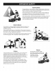
SlopeOperation You could be seriously injured or even killed if you use this unit on too steep an incline. Using the unit on a slope that is too steep or where you don't have adequate traction can cause you to lose control or roll over. 3.5ft 20.0 ft (6,0 m) A good rule of thumb is to not operate on any slope you cannot back up (in 2-wheel drive mode). You should not operate on inclines with a slope greater than a 3.5 foot rise over a 20 foot length. Always drive up and down slopes: never cross the face.
Readthesesafetyrulesandfollowthemclosely.Failuretoobeytheserulescouldresultinlossofcontrol ofunit,severepersonalinjuryordeathtoyou,or bystanders, ordamageto propertyorequipment. This mowing deck is capable The triangle _ GENERAL of amputating hands and feet and throwing in text signifies important cautions or warnings which must be followed. OPERATION 1. Read, understand, and follow all instructions in the manual and on the unit before starting. 2.
SLOPE OPERATION WARNING Slopes are a major factor related to loss-of-control and tip-over accidents, which can result in severe injury or death. Operation on all slopes requires extra caution. If you cannot back up the slope or if you feel uneasy on it, do not operate on it. Control of a walk-behind or ride-on machine sliding on a slope will not be regained by the application of the brake.
SERVICE AND MAINTENANCE Safe Handling of Gasoline 1. Extinguish all cigarettes, cigars, pipes, and other sources of ignition. 2. Use only approved gasoline containers. 3. Never remove the gas cap or add fuel with the engine running. Allow the engine to cool before refueling. 4. Never fuel the machine indoors. 5. Never store the machine or fuel container where there is an open flame, spark, or pilot light such as near a water heater or other appliance. 6.
Decal Locations (Safety and Operation) Decal - Operating Part No. 1726923 instructions, Decal - ignition Switch Positions Part No. 1722808 TO avoid injury from rotating b|ades an] thrown debris, stay char ot deck edge M a_l_ discharge. DO not mow without _d_e _et_ii! r entire gr_ss catcher in place. Danger, Rotating No. 1704277 reputation Blades, Hazard To avoid injury from rotating \\ bllades,stay _lear of deck edge;,_ Danger, Rotating Blades, Part No.
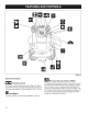
Figure 2 Control Functions Reverse __ Throttle Control The throttle controls engine speed (see Figure 2). Move the throttle forward to increase engine speed and back to decrease engine speed, Always operate at FULL throttle, Headlights The light switch turns the tractor headlights on and off. 10 Mowing Option (RMO) The Reverse Mowing Option allows for mowing (or use of other PTO driven attachments) while traveling in reverse.
D PTO Switch The PTO (Power Take-Off) switch engages and disengages attachments that use the PTO. To engage the PTO, pull UP on the switch. Push DOWN to disengage. Note that the operator must be seated firmly in the tractor seat for the PTO to function. Ignition _OFF H Stops the engine and shuts off the electrical system. RUN Allows the engine to run and powers the electrical system. _START Cranks the engine for starting.
Hourmeter Parking Brake Function The hourmeter (Figure 3) measures the number of hours the key has been in the RUN position. The hourmeter will flash an initial oil change indicator at 5 hours, and a lubrication reminder every 50 hours. These reminders display for approximately two hours and will automatically reset themselves. Applying the Parking Brake =See Figure 4.
Safety interlock System Tests This unit is equipped with safety interlock switches and other safety devices. These safety systems are present for your safety: do not attempt to bypass safety switches, and never tamper with safety devices. WARNING If the unit does not pass a safety test, do not operate it. See your authorized dealer. Test 1 -- Engine should Oil Recommendations We recommend the use of Briggs & Stratton Warranty Certified oils for best performance.
High Altitude At altitudes over 5,000 feet (1,524 meters), a minimum 85 octane/85 AKI (89 RON) gasoline is acceptable. To remain emissions compliant, high altitude adjustment is required. Operation without this adjustment will cause decreased performance, increased fuel consumption, and increased emissions. See an authorized dealer for high altitude adjustment information. Operation of the engine at altitudes below 2,500 feet (762 meters) with the high altitude kit is not recommended.
. . Clean the fuel cap area of dirt and debris. Remove the fuel cap (A, Figure 6). 1. Check the oil level. See the How to Check/Add section. Fill the fuel tank with fuel. To allow for expansion of the gasoline, do not fill above the bottom of the fuel tank neck. 2. Make sure equipment drive controls are disengaged. 3. Reinstall the fuel cap. Off 3. Move the throttle control to the FAST position. Operate the engine in the FAST position. 4. Turn the electric start switch to the ON/START position.
WARNING O The engine will shut off if the reverse ground speed pedal is depressed while the PTO is on and the RMO has not been activated. The operator should always turn the PTO off prior to driving across on roads, paths or any area that maybe used by other vehicles. Sudden loss of drive could create a hazard. ® ®® ,A WARNING Mowing in reverse can be hazardous to bystanders. Tragic accidents can occur if the operator is not alert to the presence of children. Never activate RMO if children are present.
Adjusting Mower Cutting The cutting height is adjustable and 10,2 cm). Attaching Height between 1.0" and 4.0" (2,5 The cutting height adjustment switch (A, Figure 8) controls the mower cutting height. This same switch also controls the spout rotator motor when a snowthrower is installed. The arrows on the switch correspond to the direction of adjustment (UP arrow raises cutting height, RIGHT arrow rotates the spout right, etc).
Maintenance Chart First 5 Hours Every 8 Hours or Daily Check safety interlock system Change engine oil - see engine manual Clean debris off tractor and mower deck Every 8 Hours or Daily Clean debris from engine compartment Check engine oil level - see engine manual Every 25 Hours or Annually * Every 25 Hours or Annually* Check mower blade stopping time Clean engine air filter and pre-cleaner ** Check tractor and mower for loose hardware Every 50 Hours or Annually * Change engine oil Check t
Electronic Fuel Management System The Electronic Fuel Management System monitors engine temperature, engine speed, and battery voltage to adjust the choke during engine starting and warm up. There are no adjustments on the system. If starting or operation problems occur, contact Sears Service. NOTICE: Make sure to follow the steps below or the Electronic Fuel Management System could be damaged.
/ Figure 13 Changing the Oil Used oil is a hazardous waste product and must be disposed of properly. Do not discard with household waste. Check with your local authorities, service center, or dealer for safe disposal/recycling facilities. Remove Oil 1. With engine off but still warm, disconnect the spark plug wire (A, Figure 13) and keep it away from the spark plug. 2. Remove the dipstick (D). Standard Oil Drain Plug 1. Remove the oil drain plug (B, Figure 13).
Changing Add Oil the Oil Filter For replacement intervals, see the Maintenance 1. Drain the oil from the engine. See Remove tion. Chart. Oil sec- 2. Remove the oil filter (C, Figure 14) and dispose of properly. 3. Before you install the new oil filter, lightly lubricate the oil filter gasket with fresh, clean oil. 4. Install the oil filter by hand until the gasket contacts the oil filter adapter, then tighten the oil filter 1/2 to 3/4 turns. • Place engine level.
Mower Deck Washout Port NOTE: The washout port allows you to connect a typical garden hose to the trim side (L.H.) of the mower deck to remove grass and debris from the underside. This ensures proper and safe operation of the mower. 1. Place the lawn tractor on a smooth level surface. WARNING Before running the mower, make sure the hose is properly connected and does not come into contact with the blades.
Removing the Mower Deck WARNING Engage the parking brake, disengage PTO, stop engine, and remove key before attempting to remove or install the mower deck. 1, Park the tractor on a hard, level surface such as a concrete floor. Turn off PTO switch and engine, remove the key, and apply the parking brake. 2, Place the mower in the lowest cutting position using the cutting height adjustment switch (see Features and Controls). Disconnect the cutting height wire harness. 3, Place the attachment 4.
4, Pull the idler pulley lever (D, Figure 20) to release belt tension. Install belt (E) on the PTO pulley (F). 5, Connect the inner J-bolt (C, Figure 19) to the inner lift bracket and secure with washer and cotter pin. Repeat for the other side. 6, Install the lift chain (B, Figure 18) onto hook in tractor frame and secure with cotter pin (A). Repeat for the other side. 7, Connect the cutting height wire harness plug to the tractor harness. 0 Figure 21 Installing the Mower Deck 1.
Lubricate Mower Deck Blade Lubricate the mower deck at the locations shown in Figure 23. Belt Replacement 1. Park the tractor on a smooth, level surface such as a concrete floor. Disengage the PTO, turn off the engine, and lock the parking brake. Remove the key. 2. Remove Deck). mower deck (see Removing the Mower 3. Remove screws and covers (A, Figure 24) for left and right blade spindle. 4. Remove the PTO belt (see PTO Belt Replacement). 5.
PTO Clutch Adjustment Check the PTO clutch adjustment after the initial 25 hour break-in period and then after every 250 hours of operation. Also perform the following procedure if the clutch is slipping or will not engage, or if a new clutch has been installed. 1. Remove key from ignition switch and disconnect plug wires to prevent the possibility of accidental starting while the PTO is being adjusted. spark 2.
Servicing the Mower Blades WARNING For your personal safety, do not handle the sharp mower blades with bare hands. Careless or improper handling of blades may result in serious injury. WARNING For your personal safety, blade mounting capscrews must each be installed with a hex/spline washer and spring washer, then securely tightened. Torque blade mounting capscrew to 50-60 ft-lbs (68-81 Nm). LOOSEN Figure 28 NOTE: Mower blades must be aligned perpendicular other. 1. Remove Deck).
Fuel System Storage WARNING Never store the unit (with fuel) in an enclosed, poorly ventilated structure. Fuel vapors can travel to an ignition source (such as a furnace, water heater, etc.) and cause an explosion. Fuel vapor is also toxic to humans and animals. When Storing Fuel Or Equipment ° With Fuel in Tank Store away from furnaces, stoves, water heaters or other appliances that have pilot lights or other ignition sources because they can ignite fuel vapors.
Troubleshooting the Tractor PROBLEM Engine will not turnover or start. REMEDY LOOK FOR Brake pedal not depressed. Fully depress brake pedal. PTO (electric clutch) switch is in ON position. Place in OFF position. Cruise control engaged. Move knob to NEUTRAL/OFF Out of fuel. If engine is hot, allow it to cool, then refill the fuel tank. Fuse is blown. Replace fuse or contact Sears Service. Battery terminals cleaning. require Battery discharged dead.
Troubleshooting the Tractor PROBLEM LOOK FOR Brake will not hold. Tractor steers handles hard or poorly. Troubleshooting cut is uneven. Mower cut is rough looking. stalls mower engaged. Excessive vibration. Engine easily 30 with mower runs and tractor drives, but mower not drive. Internal brake worn. Contact Sears Service. Steering Contact Sears Service. linkage is loose. Improper tire inflation. See Check Front wheel spindle bearings dry. Contact Tire Pressure section.
ENGINE Briggs K57 TRANSMiSSiON & Stratton Make Model Horsepower Displacement Electrical System Oil Capacity Briggs & Stratton® Professional SeriesTM 22 Gross HP @3400 +/- 100 rpm 40.0 cu in. (656 cc) Alternator: 16 amp DC Reg. Battery: 12 volt, 230 CCA Die Hard Gold #50784 64 oz (1,9 L) CHASSIS Fuel Tank Capacity 3.6 Gallons (13,6 L) Front Wheels Tire Size: 15 x 6.0-6 Rear Wheels Tire Size: 22 x 10.
CRAFTSMAN FULL WARRANTY FOR THREE YEARS from the date of purchase, all non-expendable ranted against any defects in material or workmanship. A defective in-home repair or replacement if repair is impossible. parts of this riding equipment are warnon-expendable part will receive free FOR FIVE YEARS from the date of purchase, the frame and front axle of this riding equipment are warranted against any defects in material or workmanship.
Congratulations on making a smart purchase. Your new Craftsman@ product is designed and manufactured for years of dependable operation. But like all products, it may require repair from time to time. That's when having a Repair Protection Agreement can save you money and aggravation.
Your Home For troubleshooting, product manuals and expert advice: managemylife www.managemylife.com For repair - in your home - of all major brand appliances, lawn and garden equipment, or heating and cooling systems, no matter who made it, no matter who sold it! For the replacement parts, accessories and owner's manuals that you need to do-it-yourself. For Sears professional installation of home appliances and items like garage door openers and water heaters.
PTS - I
Steering Group - Manual Steering CTX9000 = 107.250050 NOTE: UnJess noted otherwise, use the standard hardware torque specification chart. ............... --_ f 21; / 20 Torqueto 35_44tL IbS.
Steering REF NO Group PART - Manual NO. CTX9000-107.250050 Steering QTY.
Decal Group CTX9000 - 107.250050 NOTE: UnJess noted otherwise, use the standard hardware torque specification chart.
Decal Group REF NO PART CTX9000 - 107.250050 NO. QTY.
Electrical Group CTX9000 =107.250050 NOTE: Unless noted otherwise, use the standard hardware torque specification chart.
Electrical REF NO Group PART NO. CTX9000 =107.250050 QTY. DESCRiPTiON 1 1721810SM 1 HEADLIGHT ASSEMBLY, 2 1677371SM 4 BULB, Headlight, 12.
Controls Group CTX9000 =107.250050 NOTE: Unless noted otherwise, use the standard hardware torque specification chart.
Controls REF NO Group PART NO. CTX9000 =107.250050 QTY.
Transmission Group - Tuff Torq /(57 CTX9000 - 107.250050 NOTE: UnJess noted otherwise, use the standard hardware torque specification chart.
Transmission REF NO PART Group NO. CTX9000-107.250050 - Tuff Torq K57 QTY.
Transmission SERVICE PARTS - Tuff Torq K57A CTX9000 - 107.250050 NOTE: UnJess noted otherwise, use the standard hardware torque specification chart. ......... 87 r ...... 95 g8 _3 72 78 / 55 59 72 79 ioo24 38 3g Z7 ...........
Transmission REF NO PART SERVICE NO. PARTS QTY. CTX9000-107.250050 - Tuff Torq K57A DESCRiPTiON 2 ..... 1 *HOUSING ASSEMBLY, 3 7 1724938SM 1718052SM 1 1 HOUSING, LOWER VENT VALVE 15 8 1724279SM 2 MAGNET, K50 9 11 .....
Transmission SERVICE PARTS - Tuff Torq K57A CTX9000 - 107.250050 NOTE: UnJess noted otherwise, use the standard hardware torque specification chart. ......... 87 r ...... 95 g8 _3 72 78 / 55 59 72 79 ioo24 38 3g Z7 ...........
Transmission REF NO PART SERVICE NO. PARTS QTY. - Tuff Torq K57A CTX9000-107.250050 DESCRiPTiON 54 1724348SM 1 JERKY PLATE 55 1708689SM 1 WASHER 56 1724349SM 1 PIN, COTTER 57 58 1724296SM 1718100SM 1 1 PIN, SPRING PIN 6.0Ax 4.0 59 1707879SM 2 PACKING 60 1708692SM 1 NUT 12 61 1724955SM 1 GEAR & PINION ASSEMBLY 62 ..... 1 *GEAR, FINAL CONTR TRAC 63 1724946SM 2 COLLAR, PINION 64 ..... 1 *SHAFT, Reduction 65 1724948SM 2 WASHER, 12 x 32 x 3.
Hood, Grille & Dash Group CTX9000- 107.250050 NOTE: Unless noted otherwise, use the standard hardware torque specification chart.
Hood, Grille REF NO PART CTX9000-107.250050 & Dash Group NO. QTY.
Seat & Seat Deck Group - EVAP Compliant CTX9000 - 107.250050 NOTE: UnJess noted otherwise, use the standard hardware torque specification chart.
Seat & Seat Deck Group - EVAP Compliant REF NO PART NO. QTY. CTX9000 = 107.
Frame & Front Axle Group CTXgO00 = 107.250050 NOTE: UnJess noted otherwise, use the standard hardware torque specification chart. 7 Torqeeto 150 fl, Lhs_ (202Nnl) 3 2 i Torqueto 22-40 fl, Ibs.
Frame & Front Axle REF NO PART NO. CTX9000-107.250050 Group QTY.
Lift Group - Manual CTX9000 - 107.250050 NOTE: Unless noted otherwise, use the standard hardware torque specification chart.
Lift Group REF NO CTX9000-107.250050 - Manual PART NO. QTY.
Control Group - Cruise Control CTX9000 = 107.250050 NOTE: Unless noted otherwise, use the standard hardware torque specification chart. Lubricatebothsides o! slot with grease, Instill rounded edge el washertowardlever & bracketassembly.
Control Group REF NO PART - Cruise NO. CTX9000-107.250050 Control QTY.
Wheels & Tires Group CTXgO00- 107.250050 NOTE: UnJess noted otherwise, use the standard hardware torque specification chart.
Wheels & Tires Group REF NO PART NO. CTX9000-107.250050 QTY. DESCRiPTiON 0140 1726491SM 2 WHEEL & TIRE ASSEMBLY 0280-30) 0140-10 1727136SM 1 TIRE, 22 x 10, 10 Super Turf (Included with Ref. No. 0140) 0140-20 1726492SM 1 WHEEL, 7 x 9.97, W/3/40D 0140-30 2172353SM 2 VALVE STEM & CAP ASSEMBLY (Included with Ref. No. 0140) 0140-40 2173477SM 1 TUBE, Tire, 20 x 8, Rear (Included with Ref. No.
Engine Group - 22HP Briggs &Stratton, Twin CTX9000 - 107.250050 NOTE: UnJess noted otherwise, use the standard hardware torque specification chart.
Engine Group- REF NO PART 22HP Briggs NO. QTY. & Stratton, Twin CTX9000-107.
46" Mower Deck- Housing, Arbors & Blades CTXgO00- 107.250050 NOTE: UnJess noted otherwise, use the standard hardware torque specification chart. 0180 0220 0150 0170 0270 0130=30 0250 0250 0250 0290 0090 0310 0320........
46" Mower REF NO Deck- PART NO. Housing, QTY.
46" Mower Deck- Clutch & Support Group CTXO00- 107.250050 NOTE: UnJess noted otherwise, use the standard hardware torque specification chart. 0320 0340 0370 0220 0120 0330 UpperDrive Belt 0320 0130 0094 _: 0093 0080 -. i] ............... 0120 -_ iEF.
46" Mower REF NO Deck - Clutch PART NO. & Support QTY. Group CTX9000 = 107.250050 DESCRiPTiON 0080 1713578SM 1 ROD, 1/2 Dia. x 7-5/8 0090 1715759SM 1 ROD, 3/8 Dia.
46" Mower Deck- Height Adjust Group CTX9000 =107.250050 NOTE: UnJess noted otherwise, use the standard hardware torque specification chart.
46" Mower REF NO Deck- PART NO. Height Adjust QTY. Group CTX9000 - 107.250050 DESCRIPTION 0010 7091553YP 1 CAPSCREW, 3/8 x 1-3/4 G5 0020 5025156SM 1 WASHER, 3/8 0030 1706644SM 1 SPACER, 3/8 x 3/4 x 15/16 0040 2860681SM 2 NUT, Hex Flange Toplock, 3/8-16 0050 1931277SM 11 NUT, Hex Flange Whiz Lock, 5/16-18 0060 1960687SM 4 NUT, Hex Flange, 3/8-16, ESNA 0070 1736074AYP 2 BRACKET, Gauge Wheel, R.H. 0080 1714760SM 4 WHEEL, 2" Wide, 3-7/8 Dia.
46" Mower Deck- Height Adjust Group CTX9000 =107.250050 NOTE: UnJess noted otherwise, use the standard hardware torque specification chart.
46" Mower REF NO Deck - Height PART NO. Adjust QTY. CTX9000=107.250050 Group DESCRiPTiON 0500 1960757SM 1 NUT, Hex, LH Thread, 1/4-20 0510 1739554AYP 1 ARM, Pitch Adjustment 0520 1727103ASM 1 HANGER, L.H. 0530 1727102ASM 1 HANGER, R.H.
40H777-5136-G5 48 SHORT BLOCK 1058 OPERATOR'S MANUAL I 1329 REPLACEMENT ENGINE I 1330 REPAIR MANUAL lO_ 85O 250 21 s62 1017 1027 1013 20 220_!_ 404 _&h 552A 742 _,_ 742 _ £1._P 552 i_>_ 691 MSC000496-2 (,'_ 22 75o_._. Assembfies include aft parts shown in frames.
40H777-5136-G5 REF. NO. PART NO.
40H777-5136-G5 842 332@ 24[_ 524 _:::_ 146 741 _H 163 212 /i" 51A 929 _P 186 MSC000496- 4 Assembfies include all parts shown in frames.
40H777-5136-G5 REF. NO. PART NO. 16 796237 24 222698s 25 26 793647 791789 27 28 690975 696581 29 796209 MSC000496-5 DESCRIPTION Crankshaft Key-Flywheel (Aluminum) Piston Assembly (Standard) ....... Note ..... 793648 Piston Assembly (.020" Oversize) Ring Set (Standard) ....... Note ..... 791792 Ring Set (.020" Oversize) Lock-Piston Pin Pin-Piston Rod-Connecting REF. NO. PART NO.
40H777-5136-G5 85O 635 918 2 ,i,J_ 35 _'{(__' 1022 36 1100 _ 883 868 13 51B 1022 45 1026 -_ 1026A \_\. 85O _. 1023,_ \.% 337 1022 "_ 914 MSC000496- 6 Assembfies include aft parts shown in frames.
40H777-5136-G5 REF. NO. PART NO. 5 796231 5A 796232 7 13 693997 793988 33 34 35 697576 792200 694865 36 694865 42 499586 MSC000496- 7 REF. NO. DESCRIPTION Head-Cylinder (Cylinder 1) Head-Cylinder (Cylinder 2) Gasket-Cylinder Screw (Cylinder Head) Valve-Exhaust Valve-Intake Spring -Valve (Intake) Spring -Valve (Exhaust) Keeper-Valve Head PART NO.
40H777-5136-G5 1169 654 672 so 231 108_i @ 633 217 1124A 1126g 1124 _; 318 _'_ 318A%# 51A 137 163 276 dD _J 240 J 918 J 387 1436 MSC000496- 8 Assembfies include all parts shown in frames.
40H777-5136-G5 REF. NO. PART NO.
40H777-5136-G5 1036 EMiSSiONS LABEL 306 306A 74_ 307 _ 307A 964 ,_ 467 u 186B 918A f "_> 1040 304 305A 967 865 447 964_1 573 163 197 MSC000496-10 Assembfies include all parts shown in frames.
40H777-5136-G5 RER NO. PART NO. 73 74 494439 698425 163 186A 691001 799158 186B 845141 197 697820 304 305 799955 691005 305A 790690 DESCRIPTION Screen-Rotating Screw (Rotating Screen) Gasket-Air Cleaner Connector-Hose (EVAP System) Connector-Hose (EVAP System) Screw (Back Plate) Housing-Blower Screw (Blower Housing) (1/4-20x.66) Screw (Blower Housing to intake Elbow) MSC000496-11 REF. NO. 306 PART NO. 798855 DESCRIPTION RER NO. PART NO.
40H777-5136-G5 1070 222 1005 188 _ 216 265 209_ I_ 267 332 _, 75 (o_ 334 II 23 635 367 729 .................... 526 1119 '!_ 501 789 .... jJ-J ..... 309 1439 697 MSC000496-12 Assembfies include aft parts shown in frames.
40H777-5136-G5 REE NO. PART NO. 23 75 799090 691056 Flywheel Washer 332 691059 188 691108 (Flywheel) Screw 333 334 799651 691061 209 798921 367 697820 211 691019 216 222 265 267 796879 798916 691024 792629 474 501 526 696458 797375 691108 635 640 692076 796913 697 791680 309 590476 MSC000496-13 REF. NO.
40H777-5136-G5 121 CARBURETOR OVERHAUL 137 KIT 987 217 150 1123 #-_) 633 ® 163 1124 ,_ _, 633A Q 104 _ 276 276A 105 1124A C-'9 _*_ _ 1353 F_j) [_] 276B _ 358 ENGINE GASKET SET 51B 163 524 d>) 691 (_ 842 _',_ 12 868 943 <_ 20 943A 1022 _i;_-___\-.?, 1095 VALVE GASKET SET 868 _,_' 883 51B 1022 163 MSC000496-14 Assembfies include all parts shown in frames.
40H777-5136-G5 REF. NO. PART NO. 3 391086s 7 9 12 20 51 51A 51B 104 105 137 150 163 121 693997 690937 697227 795387 795123 690950 690949 694918 797410 690994 690995 691001 797890 MSC000496-15 DESCRIPTION Seal-Oil (Magneto Side) Gasket-Cylinder Head Gasket-Breather Gasket-Crankcase Seal-Oil (PTO Side) Gasket-Intake Gasket-Intake Gasket-Intake Pin-Float Hinge Valve-Float Needle Gasket-Float Bowl Gasket- Nozzle Gasket-Air Cleaner Kit Carburetor Overhaul REF. NO. PART NO.
Torque Specification Chart Torque Specification Chart FORSTANDARDMETRICMACHINEHARDWARE(Tolerance± 20%) FORSTANDARDMACHINEHARDWARE(Tolerance+20%) ® Properly Class _ddeware _ SAEGrade2 Class8.8 SizeOf in/Ibs Hardwareft/Ibs in/Ibs fl/Ibs Nm. .56 5.88 13.44 1.28 26.4 2.5O 44,64 4.3 5.2 7.1 7.7 10.5 15 21 26 36 42 58 64 88 89 121 126 17! 169 23O 217 295 326 435 435 590 599 8OO 759 1030 988 1340 M3 M4 M5 M6 M7 M8 MIO M12 M14 M16 M18 M20 M22 M24 M27 M30 M33 M36 M39 in/Ibs fl/]bs Nm.
Manual Del Due_o CRRFTSMRH ° CTX 9000 Tractor para c_sped Modelo N° 107.250050 (22HP brutos Briggs & Stratton con cortacesped de 46 pulg.) Para obtener respuestas a sus preguntas sobre este producto, Ilame al: Linea de ayuda de Sears Craftsman 1-800-659-5917. Sears Brands Management Corporation, Visite nuestro sitio Web de Craftsman: www.craftsman.com Hoffman Estates, IL 60179 EE.
Tapa delantera ............................................................................................................ I Seguridad del operador ............................................................................................. 4 Caracteristicas y controles ..................................................................................... 10 Funcionarniento ........................................................................................................
Manejarel equipoconseguridad Felicidades por haber adquirido un equipo de jardin y campo de alta calidad. Nuestros productos estan dise_ados y fabricados para cumplir o exceder todas las normas de seguridad del sector. El equipo electronico solamente es seguro dependiendo de como Io utilice el operador. Si se utiliza de manera incorrecta o si no se Ileva a cabo un mantenimiento correcto, ipuede ser peligroso! Recuerde que usted es el responsable de su seguridad y de la de aquellos que le rodean.
Funcionamiento encuestas Podria lesionarse gravemente o incluso matarse si utiliza esta unidad en cuestas demasiado pronunciadas. El uso de la unidad en una pendiente que sea demasiado pronunciada o donde no posea la traccion adecuada puede hacer que pierda el control o que vuelque. Un buen consejo es no utilizar la maquina en ninguna pendiente sobre la que no pueda ir marcha atras (en modo traccion a dos ruedas).
Lea estas perdida normas det control de seguridad y respetetas de la unidad, cerca, o podria causar manos y pies y lanzar da_os lesiones en la propiedad objetos. estrictamente. personates En el texto, Et no respetar graves o en el equipo. el tria_ngulo ,_ o la muerte La cubJerta significa estas normas del usuario podria dar como resultado o de terceros del cortac_sped que debe seguir la que se encuentren puede precauciones Ilegar a arnputar o advertencias importantes.
FUNCIONAMIENTO EN PENDIENTES Las pendientes son un factor de gran p@dida en los casos de p@dida de control y en los accidentes en los que vuelca el cortacesped, que pueden resultar en lesiones graves o incluso la muerte. La operaci6n en todo tipo de pendientes requiere una precauc_on a_adida. Si no puede ir hacia atra_ssobre una pendiente con el cortacesped o no se siente seguro sobre la pendiente, no la utilice la unidad sobre ella.
REPARACION Y MANTENIMIENTO S_ker hantering av bensin 1. Apague todos los cigarrillos, puros, pipas y cualquier otra fuente de ignici6n. 2. Utilice t_nicamente contenedores de gasolina homologados. 3. No retire la tapa de la gasolina ni reponga combustible con el motor en funcionamiento. LAt motorn svalna innan den fylls pA. 4. No Ilene el dep6sito de la mAquina en espacios cerrados. 5.
Ubicaciones de las calcomanias (Seguridad y funcionamiento) Calcomania - Instrucciones N° de plaza 1726923 de funcionamiento Calcomania - Posiciones del interruptor de ignicion N° de pieza 1722806 thr0wn debris, stay r_ear 0t deck edge _, Peligro, cuchillas giratorias N ° de pieza 1704277 _Amputation \\ Hazard \\ Toavoid injurytram rotating \\ _=odaa, ata, 0,0a, atd0,,0,_,,\\ Peligro, cuchillas giratorias N° de pieza 1704276 Calcomania - Control de velocidad de crucero y elevacion de accesor
Figura 2 Funciones de control Control de la mariposa La mariposa controla la velocidad det motor (consutte Figura 2). Mueva la mariposa hacia delante para aumentar la velocidad det motor y hacia atr,_s para disminuirla. Siempre opere a TODA MARCHA. Faros El interruptor de luz enciende y apaga los faros del tractor.
_ Interruptor PTO Control de velocidad Et interruptor PTO (toma de fuerza) acopta y desacopta accesorios que utilizan PTO. Para acoplar PTO, tire hacia ARRIBA del interruptor. Empuje hacia ABAJO para el desacople. Recuerde que el usuario debe estar sentado firmemente en el asiento de! tractor para que funcione PTO. Interruptor de encendido El interruptor de encendido arranca y detiene el motor; tiene tres posiciones: _ APAGAR Detiene el motor y apaga el sistema electrico.
Contador horatio Funci6n del freno de estacionamiento El contador horario (Figura 4) mide la cantidad de horas que la Ilave Ileva puesta en la posicion de ENCENDIDO. El contador horario hara parpadear la luz del indicador de cambio de aceite inicial alas 5 horas de uso y un recordatorio de lubricacion cada 50 horas. Estos recordatorios se muestran pot aproximadamente horas y se reestableceran automaticamente.
Pruebas del sistema de interbloqueo de seguridad Esta unidad estA equipada con los conmutadores de interbloqueo de seguridad y otros dispositivos de seguridad. Estos sistemas de seguridad se utilizan por su seguridad. No intente modificar los dispositivos de seguridad y no fuerce nunca los dispositivos de seguridad. ADVERTENCIA Si la unidad no pasa con exito alg_n test de seguridad, no la ponga en funcionamiento. Consulte a su distribuidor autorizado.
Alta altitud Para altitudes superiores a 5.000 pies (1.524 metros), es aceptable el uso de gasolina con un minimo de 85 octanos/85 AKI (89 RON). Para cumplir con las emisiones, se requiere hacer un ajuste para alta altitud. Si la operaci6n se realizar sin haber hecho este ajuste se causarb, una disminuci6n en el rendimiento, un aumento del consumo de combustible y un aumento en las emisiones. Consulte a un distribuidor autorizado para obtener informaci6n sobre el ajuste para altitudes altas.
1, Limpie el Area de la tapa de combustible desechos. Retire la tapa de combustible de polvo y (A, Figura 6). 1. Compruebe el nivel de aceite. Consulte la secci6n C6mo verificar/a#adir aceite. 2. Llene el tanque de combustible con combustible. Para permitir la expansi6n de la gasolina, no Io Ilene por encima de la parte inferior del cuello del tanque de combustible. 2. Asegurese de que los controles del arranque del equipo esten desenganchados. 3.
ADVERTENCIA El motor se apagara si presiona el pedal de la velocidad de avarice marcha atras mientras la toma de fuerza esta activada y el corte de cesped marcha atr_s no se ha activado. El operador siempre debe apagar la toma de fuerza antes de cruzar calles, caminos o cualquier zona por donde puedan transitar otros vehiculos. Si pierde el control de la conducci6n de manera repentina, puede resultar peligroso. ® ADVERTENCIA El corte de cesped marcha atr_s puede ser peligroso para los transe_ntes.
Enganche Ajustar la altura de corte del cortac6sped La altura de corte puede ajustarse entre 1,0" y 4,0" (2,5 y 10,2 cm).
U nderh llsschema i Revisar el sistema de bloqueo de seguridad Limpiar el tractor y el cortacesped gang per at* Kontrollera stopptiden f6r klipparens blad Revisar tractor/cortacesped por si tuviesen piezas sueltas Verificar la presion de los neumaticos ii i iii iiiiiiiiiiiiiiiiiiiiiiiiiiiiiiii Comprobacion del nivel de aceite del motor - consulte el manual del motor __ _ Vat 25:e timma eHer en gang per ar _ Limpiar el filtro y el depurador de aire del motor ** Vat 50:e timma eller en gang per at* Byt mo
Sistema electr6nico combustible de manejo del Lirnpiar la bateria y el cableado ADVERTENCIA El sistema Electr6nico de Manejo del Combustible supervisa la temperatura del motor, la velocidad del motor, y el voltaje de la bateria para ajustar el estrangulador durante el arranque y el calentamiento del motor. No existen ajustes en el sistema. Si se presentaran problemas en el arranque o en la operaci6n, p6ngase en contacto con el servicio tecnico de Sears.
Figura13 C6mo cambiar el aceite Esta unidad no tiene un freno que se pueda ajustar manualmente. Si el freno no funciona correctamente, hable con su distribuidor. Remocibn del aceite Tap6n de drenaje de aceite estandar 1. Remueva el tapon de drenaje de aceite (B, Figura 13). Drene el aceite en un recipiente aprobado. 2. Despues de haber drenado el aceite del motor, instale y apriete el tapon de drenaje de aceite. 1.
Cambie el fiJtro de aceite Aprovisionamiento de aceite Para saber cada cuanto requiere ser reemplazado, consulte el cuadro de Mantenimiento. • Coloque el motor a nivel. 1. Drene el aceite del motor. Consulte la seccion Remocidn del aceite. • Limpie el area de Ilenado de aceite de todo desecho. • Consulte la seccion de Especificaciones pacidad de aceite. 2. Remueva el filtro de aceite (C, Figura 14) y desechelo de manera adecuada. . . .
Puerto de lavado de la plataforma cortacesped del NOTA: El puerto de lavado le permite conectar una manguera de jardin tipica al lado de corte (izquierdo) de la plataforma del cortacesped para quitar el cesped y desechos de su parte inferior. Esto garantiza el funcionamiento seguro y correcto de/cortacesped. 1. Coloque el tractor cortacesped nivelada.
Cbmo quitar Ja plataforma cortacespedes del ADVERTENCIA Accione el freno de mano, suelte la toma de fuerza, apague el motor y quite la llave antes de intentar quitar o instalar la plataforma del cortacespedes. 1. Estacione el tractor en una superficie dura y nivelada, como un piso de concreto. Apague el interruptor de la toma de fuerza y el motor, quite la Ilave y aplique el freno de mano. 2.
4, Jale la palanca de la polea libre (D, Figura 20) para liberar la tensidn de la correa. Instale la correa (E) en la polea de la toma de fuerza (F). 5, Conecte el cerrojo J interno (C, Figura 19) a la abrazadera de elevaci6n interna y asegure con su arandela y pasador de chaveta. Repita en el otro lado. 6, Instale la cadena de elevaci6n (B, Figura 18) en el gancho en el marco del tractor y asegure con el pasador de chaveta (A). Repita en el otro lado.
Lubrique la plataforma cortacespedes del Reemplazo Lubrique la plataforma del cortaces 3edes en las ubicaciones mostradas en la Figura 23. de la correa de la cuchUla 1. Estacione el tractor en una superficie lisa y nivelada, como un piso de concreto. Desconecte la toma de fuerza, apague el motor y active el freno de mano. Quite la Ilave. 2. Quite la plataforma del cortacespedes (vet Cdmo quitar la plataforma del cortac_spedes). 3.
Ajuste del embrague fuerza de la toma de Verifique el ajuste del embrague de la toma de fuerza despues del periodo inicial de 25 horas de despegue del motor y luego despues de cada 250 horas de operaci6n. Tambien realice el procedimiento siguiente si el embrague resbala o no engancha, o si ha sido instalado un nuevo embrague. 1. Quite la Ilave del interruptor de encendido y desconecte los cables de las bujias para prevenir la posibilidad de un encendido accidental mientras es ajustada la toma de fuerza.
Prestar servicio cortacespedes a las cuchillas del ADVERTENCIA Para su seguridad personal, no manipule las cuchillas afiladas del cortacespedes con las manos descubiertas. El manejo descuidado o inadecuado de las cuehillas puede tener como resultado heridas graves.
AImacenaje ADVERTENCIA Nunca almacene la unidad (con combustible) en una estructura cerrada y con poca ventilaci6n. Los vapores del combustible pueden trasladarse a una fuente de ignici6n (tal como una caldera, un calentador de agua, etc.) y causar una explosi6n. El vapor del combustible tambien es t6×ico para seres humanos y animales.
PROBLEIVIA BUSQUE SOLUCK_N El pedal del freno no esta presionado. Presione por completo el pedal del freno. El interruptor de toma de fuerza (embrague etectrico) se encuentra en la posicion de ENCENDIDO. Coloquelo en la posicion de apagado. El control de crucero esta accionado. Mueva la peritla a la posicion de NEUTRO/APAGADO. Combustible agotado. Si et motor esta catiente, dejelo enfriar y vuelva a Itenar el deposito de combustible. El fusible esta quemado.
Localizaci6n de fallas del tractor PROBLEMA BUSQUE i El freno no se mantiene. La direcci6n del tractor est_ dura o su manejo es deficiente. Localizaci6n SOLUCION El freno interno estA desgastado. Pongase en contacto con el servicio tecnico de Sears. La conexion de la direccion esta suelta. Pongase en contacto con el servicio tecnico de Sears. Inflado incorrecto de los neumaticos. Consulte la secci6n neumbticos. Los rodamientos del eje de la rueda delantera estAn secos.
MOTOR Briggs TRANSMISI6N & Stratton Fabricado por Modelo Caballos de fuerza Briggs & Stratton® Professional Series Desplazamiento Sistema electrico Capacidad TM 22 Gross HP @ 3400 +/- 100 rpm 40,0 cu pulg. (656 cc) AIternador: 16 amperios DC Reg.
GARANTJA TOTALDEFABRICACION DURANTE UNPERJODO DETRESANOSacontardesdelafechadecompra,todaslaspiezasnosujetasa desgaste deesteequipoestangarantizadas contracualquierdefectodematerialo manodeobra.Cualquierpiezanosujetaa desgastedefectuosa serareparada demaneragratuitaa domicilioo serareemplazada si esimposiblerepararla. DURANTE UNPERJODO DECINCOANOSa contardesdelafechadecompra,elarmazony el ejedelantero deeste equipoestangarantizados contracualquierdefectodematerialo manodeobra.
Felicitaciones por su compra inteligente. Su nuevo producto Craftsman @ fue dise_ado y fabricado para a_os de funcionamiento confiable. Pero como todos los productos, puede requerir reparaci6n de vez en cuando. Ese es el momento en que unAcuerdo de Protecci6n para Reparaciones puede ahorrarle dinero y dolores de cabeza.
Your Home For troubleshooting, product manuals and expert advice: managemylife www.managemylife.com For repair - in your home - of all major brand appliances, lawn and garden equipment, or heating and cooling systems, no matter who made it, no matter who sold it! For the replacement parts, accessories and owner's manuals that you need to do-it-yourself. For Sears professional installation of home appliances and items like garage door openers and water heaters.