MAN OPERATOR' AL T$ 10 in. TABLE SAW Model No. 315.284610 A WARNING: To reduce the risk of injury, the user must read and understand the operator's manual before using this product. Customer Help Line: 1-800-932-3188 Product distributed Hoffman Estates, Visit the Craftsman 988000-118 5-18-10 (REV:01) in the United States by Sears Brands Management IL 60179 web page: www.sears.
This tool has many features for making its use more pleasant and enjoyable. Safety, performance, and dependability have been given top priority in the design of this product making it easy to maintain and operate. ONE YEAR FULL WARRANTY ON CRAFTSMAN TOOL If this Craftsman tool fails due to a defect in material or workmanship within one year from the date of purchase. Call 1-800-4-MY-HOME ® to arrange for free repair.
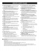
_l_ WARNING: Read and understand all instruc- tions. Failure to follow all instructions listed below, may result in electric shock, fire and/or serious personal injury. READ ALL INSTRUCTIONS [] KNOW YOUR POWER TOOL. Read the operator's manual carefully. Learn the saw's applications and limitations as well as the specific potential hazards related to this tool. [] GUARD AGAINST ELECTRICAL SHOCK BY PREVENTING BODY CONTACT WITH GROUNDED SURFACES.
[] [] KEEP HANDS AWAY FROM CUTTING AREA. Keep hands away from blades. Do not reach underneath work or around or over the blade while blade is rotating. Do not attempt to remove cut material when blade is moving. BLADE COASTS AFTER BEING TURNED OFF. [] NEVER USE IN AN EXPLOSIVE ATMOSPHERE. Normal sparking of the motor could ignite fumes. [] INSPECT TOOL CORDS PERIODICALLY. if damaged, have repaired by a qualified service technician at an authorized service facility.
[] ALWAYS SECURE WORKfirmlyagainstthe ripfence or mitergauge.NEVERusetheripfenceduringthe sameoperationasthe mitergauge. [] WHENMAKING NON=THROUGH RiP CUTS, always use a push stick, push block, and/or featherboard so your hands do not come within 3 inches of the saw blade. [] WHEN RIPPING NARROW STOCK, always use a push stick, push block, or featherboard. [] NEVER perform any operation "freehand" which means using only your hands to support or guide the workpiece.
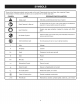
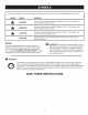
Someofthefollowingsymbolsmaybeusedonthistool.Pleasestudythemandlearntheirmeaning.Proper interpretation ofthesesymbolswillallowyouto operatethetool betterandsafer. SYMBOL NAME DESIG NATION/EXPLANATION Safety Alert Indicates a potential personal injury hazard. @ Read Operator's Manual To reduce the risk of injury, user must read and understand operator's manual before using this product. 0 Eye Protection Always wear eye protection Z87.1.
Thefollowingsignalwordsandmeanings areintendedto explainthelevelsofriskassociated withthisproduct. SYMBOL SIGNAL MEANING DANGER: Indicates an imminently hazardous situation, which, if not avoided, will result in death or serious injury. WARNING: Indicates a potentially hazardous situation, which, if not avoided, could result in death or serious injury. CAUTION: Indicates a potentially hazardous result in minor or moderate injury.
EXTENSION CORDS SPEED Use only 3-wire extension cords that have 3-prong grounding plugs and 3-pole receptacles that accept the tool's plug. When using a power tool at a considerable distance from the power source, use an extension cord heavy enough to carry the current that the tool will draw. An undersized extension cord will cause a drop in line voltage, resulting in a loss of power and causing the motor to overheat.
Anti=KickbackPawls (flooring, radial arm, and table saws} A device which, when properly installed and maintained, is designed to stop the workpiece from being kicked back toward the front of the saw during a ripping operation. Arbor The shaft on which a blade or cutting tool is mounted. Bevel Cut A cutting operation made with the blade at any angle other than 90 ° to the table surface. Compound Cut A cross cut made with both a miter and a bevel angle.
PRODUCT SPECiFiCATiONS Blade Arbor .............................................................. Blade Diameter .......................................................... Blade Tilt ................................................................ Rating .................................................. 5/8 in. 10 in. Input ..................................................................... 15 Amps No Load Speed .................................... 5,000 r/min. (RPM) 0° - 45 ° Cutting Depth at 0 °.
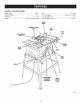
KNOWYOURTABLESAW HEIGHT/BEVEL ADJUSTING HANDWHEELLocated on the front of the cabinet, use this handwheel to lower and raise the blade for height adjustments or blade replacement. This handwheel also makes the adjustment for bevel angles easy. See Figure 2. The safe use of this product requires an understanding of the information on the tool and in this operator's manual as well as a knowledge of the project you are attempting.
OPERATING COMPONENTS WARNING: ALWAYS remove the switch key when the tool is not in use and keep it in a safe place. In the event of a power failure, turn the switch off ( O ) and remove the key. This action will prevent the tool from accidentally starting when power returns. The upper portion of the blade projects up through the table and is surrounded by an insert called the throat plate. The height of the blade is set with a handwheel on the front of the cabinet.
BLADES For maximum performance, it is recommended that you use the 24-tooth, 10 in. carbide-tipped combination blade provided with your saw. Additional blade styles of the same high quality are available for specific operations such as ripping. Your local dealer can provide you with complete information. ,_ WARNING: Do not use blades rated less than the speed of this tool. Failure to heed this warning could result in personal injury.
Thefollowingitemsareincludedwiththetablesaw: 0 E A Fig.5 A. Anti-Kickback Pawls................................................ 1 H. Screw....................................................................... 2 B. BladeGuard............................................................. 1 I. OpenEndWrench .................................................... 1 J. ClosedEndWrench................................................. 1 C. SwitchKey...............................................................
The following items are included with the table saw leg stand: I F F Fig. 6 A. Lower Brace .............................................................. 2 R Carriage Bolt (1/4 - 20 x 1/2 in.) .............................. 16 B. Lower Side Brace ...................................................... 2 G. Carriage Bolt (1/4 - 20 x 1-3/8 in.)............................. 4 C. Upper Brace .............................................................. 2 H Foot .......................................
UNPACKING This product requires assembly. ,_ [] Carefully lift saw from the carton and place it on a level work surface. NOTE: This tool is heavy. To avoid back injury, keep your knees bent and lift with your legs, not your back, and get help when needed. A A WARNING: Do not use this product if any parts on the Loose Parts List are already assembled to your product when you unpack it. Parts on this list are not assembled to the product by the manufacturer and require customer installation.
TO ASSEMBLE See Figure 7. THE LEG STAND MOUNTING THE TABLE STAND See Figure 8. Assembly is best done in the area where the saw will be used. If you are unsure about the description of any part, refer to the drawing. If any parts are missing, delay assembling until you have obtained the missing part(s). SAW BASE ON THE LEG [] Take the following from a small hardware pack: 4 carriage bolts (1/4-20 x 1-3/8 in.
TO INSTALL THE HANDLE TO INSTALL THE LOCKING See Figure 10. See Figure 9. [] [] Slide the locking lever over the exposed end of the rip fence making certain the handle is inserted as far as possible. Hold the nylon nut securely and turn the screw counter- clockwise to remove the nut completely. NOTE: Do not remove the screw from the handle. [] Align the holes in the rip fence and the holes in the lever. Secure using the screws.
TO CHANGE BETWEEN RiViNG KNIFE See Figure 12. A SPREADER AND A _"-=-"_---_ NOTE: The spreader/riving knife must be placed in the through cutting, or "up" position (spreader position), for all other cutting operations. (UNLOCKED) ,( [] Unplug the saw. (or "up" position RELEASE LEVER \ This saw is shipped with the spreader/riving knife placed in the non-through cutting or "down" position (riving knife position). To place in spreader position through cutting): [] Remove the throat plate.
TO CHECK SAW BLADE See Figure 13. iNSTALLATiON TO INSTALL THE BLADE KICKBACK PAWLS See Figures 14- 16. CAUTION: To work properly, the saw blade teeth must point down toward the front of the saw. Failure to do so could cause damage to the saw blade, the saw, or the workpiece. Unplug the saw. NOTE: Anti-kickback [] Lower the saw blade and remove the throat plate. through cuts. [] Make sure the bevel locking lever is securely pushed to the right.
Toinstall [] anti=kickback pawls: Press and hold the button on the right side of the antikickback pawls. TO CHECK AND ALIGN THE SPREADER/RIVING KNIFE AND SAW BLADE See Figures 17- 18. [] Align the slot in the pawls over the rear hole in the spreader/riving knife. [] To check alignment [] Unplug the saw. Push the pawl handle down snapping them into place and release the button. knife: [] Raise the saw blade by turning the height/bevel adjusting handwheel clockwise.
Toadjust(horizontally): [] Removethebladeguardassemblyandanti-kickback pawls. [] Raisethebladeto itsfullheight. [] Insertthehexkeythroughtheslotonthebackofthe saw.Twoadjustmentscrewscanbeaccessedthrough theslot. [] Turntheadjustmentscrewsto reposition thespreader/ rivingknifeleftor rightas neededto alignthespreader/ rivingknifewiththesawblade. [] Onceproperlyaligned,securelyretightenthescrews. To adjust (vertically): [] Push either side of the riving knife to align it top to bottom with the blade.
A Kickback can be caused by any action that pinches the blade in the wood such as: WARNING: Do not allow familiarity with tools to make you careless. Remember that a careless fraction of a second is sufficient to inflict severe injury. [] Making a cut with incorrect blade depth [] Sawing into knots or nails in the workpiece A A A [] Twisting the wood while making a cut WARNING: Always wear eye protection with side shields marked to comply with ANSI Z87.1.
CUTTINGAIDS See Figure 20. Push sticks are devices that may be used for pushing a workpiece through the blade in any rip cut. When making non-through cuts or ripping narrow stock, always use a push stick, push block, and/or featherboard so your hands do not come within 3 inches of the saw blade. They can be made in various sizes and shapes from scrap wood and used in a specific project. The stick must be narrower than the workpiece, with a 90 ° notch in one end and shaping for a grip on the other end.
FEATHERBOARD A featherboard is a device used to help control the workpiece by holding it securely against the table or fence. Featherboards are especially useful when ripping small workpieces and for completing non-through cuts. The end is angled with a number of short kerfs to give a friction hold on the workpiece and locked in place on the table with a C-clamp. Test to ensure it can resist kickback. FEATHERBOARD HOW TO MAKE A FEATHERBOARD See Figure 23.
TYPESOF CUTS See Figure 25. © There are six basic cuts: 1) the cross cut, 2) the rip cut, 3) the miter cut, 4) the bevel cross cut, 5) the bevel rip cut, and 6) the compound (bevel) miter cut. All other cuts are combinations of these basic six. Operating procedures for making each kind of cut are given later in this section. A WARNING: Always make sure the blade guard and anti-kickback pawls are in place and working properly when making these cuts to avoid possible injury.
TO CHANGE BLADE See Figure 26. DEPTH 900ADJUSTMENT SCREW 450 ADJUSTMENT SCREW The blade depth should be set so that the outer points of the blade are higher than the workpiece by approximately 1/8 in. to 1/4 in. but the lowest points (gullets) are below the top surface. BEVEL [] Turn the bevel lock lever to the right. [] LEVER Raise the blade by turning the height/bevel adjusting handwheel clockwise or lower it by turning the handwheel counterclockwise.
A TO SET THE RiP FENCE THE BLADE See Figure 30. WARNING: To reduce the risk of injury, always make sure the rip fence is parallel to the blade before beginning any operation. [] Place the rear lip on the rear of the saw table and pull slightly toward the front of the unit. [] Lower the front end of the rip fence onto the guide surfaces on top of the front rail. TO NOTE: The anti-kickback pawls and blade guard assembly must be removed to perform this adjustment.
TO USE THE MITER See Figure 31. GAUGE TO USE THE MITER GAUGE IN A REVERSE POSITION See Figure 32. The miter gauge provides greater accuracy in angled cuts. For very close tolerances, test cuts are recommended. For larger workpieces, the miter gauge can be reversed in the miter gauge grooves. It will be necessary when reversing the miter gauge to clamp the workpiece to the miter gauge body. There are two miter gauge grooves, one on either side of the blade.
HEELING (PARALLELING) MITER GAUGE GROOVE See Figures 33 - 35. A THE BLADE RIGHTMITER GAUGEGROOVE TO THE ADJUSTING SCREWS WARNING: The blade must be parallel to the miter gauge groove so the wood does not bind resulting in kickback. Failure to do so could result in serious personal injury. Do not loosen any screws for this adjustment until you have checked with a square and made test cuts to be sure adjustments are necessary. Once the screws are loosened, these items must be reset. [] Unplug the saw.
MAKING CUTS CROSSCUT PLACERIGHTHANDON MITERGAUGEHERE This table saw can perform a variety of cuts that are not all mentioned in this manual. DO NOT attempt to make any cuts not covered here unless you are thoroughly familiar with the proper procedures and necessary accessories. Your local library has many books on table saw usage and specialized woodworking procedures for your reference. The blade provided with the saw is a high-quality combination blade suitable for ripping and cross cut operations.
MAKING MAKING A RiP CUT See Figure 38, _lL WARNING: A MITER CUT See Figure 39. A Make sure the blade guard assembly is installed and working properly to avoid serious possible injury. WARNING: Make sure the blade guard assembly is installed and working properly to avoid possible serious injury. [] Set the blade to the correct depth for the workpiece. [] Remove the rip fence. [] Position the rip fence the desired distance from the blade for the cut and securely lock the handle.
MAKINGA BEVELCROSSCUT BEVELCROSSCUT See Figures 40 - 41. WARNING: MITERGAUGE STRAIGHT BLADE ANGLED Make sure the blade guard assembly is installed and working properly to avoid possible serious injury. A WARNING: The miter gauge must be on the left side of the blade to avoid trapping the wood and causing kickback and the risk of serious personal injury. [] Remove the rip fence. [] Unlock the bevel locking lever. [] Adjust the bevel angle to the desired setting. [] Lock the bevel locking lever.
[] Make sure the wood is clear of the blade before turning on the saw. MAKING A COMPOUND See Figure 43. [] When ripping a long workpiece, place a support the same height as the table surface behind the saw for the cut work. ,t_ m [] Turn the saw on. [] A Position the workpiece flat on the table with the edge flush against the rip fence. Let the blade build up to full speed before feeding the workpiece into the blade.
MAKING A NON=THROUGH See Figure 44. _, WARNING: NON-THROUGH CUT CUT BLADEGUARD REMOVED DO NOT install dado blades on this machine. The arbor shaft has insufficient threads to mount a dado blade. Mounting a dado blade could result in the risk of serious personal injury. Non-through cuts (made with a standard 10 in. blade) can be made with the grain (ripping) or across the grain (cross cut). The use of a non-through cut is essential to cutting grooves.
WARNING:Beforeperforming anyadjustment, ARBOR SHAFT make sure the tool is unplugged from the power supply and the switch is in the OFF position. Failure to heed this warning could result in serious personal injury. BLADE BLADE WASHER BLADE The table saw has been adjusted at the factory for making very accurate cuts. However, some of the components might have been jarred out of alignment during shipping. Also, over a period of time, readjustment will probably become necessary due to wear.
0° ADJUSTMENT 45° ADJUSTMENT SCREW SCREW [] Place a combination left. square beside the blade on the [] Turn the 0 ° adjustment screw until the saw blade starts to move. Check again for squareness and continue to adjust if needed. if the blade is not an exact 45°: [] Loosen the adjustment screw. ® [] Unlock the bevel locking lever. [] Push the handle to the right side of the slot. Lock the angle by pushing the bevel locking lever. [] Place a combination left. Fig.
TO CHECK THE ALIGNMENT TO THE BLADE See Figure 51. OF THE RiP FENCE [] Unplug the saw. [] Raise the locking lever to permit the rip fence to be moved. [] Place a framing square beside the blade and move the rip fence up to the square. Take the dimension on the rip scale. [] Move the fence back and turn the framing square 180 ° to check the other side. [] if the two dimensions are not the same, loosen the two bolts on the fence and align it. [] Retighten the two bolts.
i ROBLEM Excess vibration. CAUSE SOLUTION ] Blade is out of balance. Replace blade. Blade is damaged. Replace blade. Saw is not mounted securely. Tighten all hardware. Work surface is uneven. Reposition on flat surface. Blade is warped. Check saw blade installation. Replace blade if necessary. Rip fence does not move Rip fence not mounted correctly. Remount the rip fence. Rails are dirty or sticky. Clean and wax rails. Clamp screw is out of adjustment.
I PROBLEM CAUSE SOLUTION Saw does not make accurate Positive stops inside cabinet need 90 ° or 45 ° cuts. adjusting (Bevel Cuts). Miter gauge is misaligned (Miter Adjust positive stops. Adjust the miter gauge. Cuts). Height/bevel adjusting hand- Gears or screw post inside wheel is hard to turn. cabinet are clogged with saw dust. Saw does not start. Motor cord or wall cord is not Clean the gears or screw post. Plug in motor cord or wall cord. plugged in. Blade makes poor cuts.
_- CRAFTSMAN 10 in. TABLE SAW- MODEL NUMBER 315.
_- CRAFTSMAN 10 in. TABLE SAW- MODEL NUMBER 315.284610 The 10 in, model PORTABLE number TABLE will be found SAW or onwhen a labelordering attachedparts. to the cabinet. Always mention the model number in all correspondence PARTS LIST FOR FIGURE KEY NO. PART NUMBER DESCRIPTION 1 089110120001 Throat Plate Assembly ..................................... 1 2 089015001001 Screw (M8 x 30 mm) ........................................ 3 089015001013 Screw (M8 x 35 mm) ..............................
CRAFTSMAN 10 in. TABLE SAW- MODEL NUMBER 315.284610 The 10 in, model PORTABLE number TABLE will be found SAW or onwhen a labelordering attachedparts. to the cabinet. Always mention the model number in all correspondence PARTS LIST FOR FIGURE KEY NO. PART NUMBER 57 089037007700 DESCRIPTION QTY Blade Guard Assembly (Inc. Key Nos. 51-56) ....................................... KEY NO. regarding your A PART NUMBER DESCRIPTION Washer (D6.5 x D20 x 1.6t) ..............................
_- CRAFTSMAN 10 in. TABLE SAW- MODEL 2 NUMBER 315.
CRAFTSMAN 10 in. TABLE SAW- MODEL NUMBER 315.284610 The 10 in. model PORTABLE number TABLE will be found SAW or onwhen a labelordering attachedparts. to the cabinet. Always mention the model number in all correspondence PARTS LiST FOR FIGURE KEY NO. PART NUMBER DESCRiPTiON 1 089110120006 Cabinet ........................................................... 1 2 080015001473 Screw (M4 x 7 mm, Flat Hd.) .......................... 3 089110120900 Front Panel Label .................................
CRAFTSMAN 10 in. TABLE SAW- MODEL NUMBER 315.284610 The 10 in, model PORTABLE number TABLE will be found SAW or onwhen a labelordering attachedparts. to the cabinet. Always mention the model number in all correspondence regarding your 3 2 8 FIGURE C PARTS LIST FOR FIGURE KEY NO. PART NUMBER DESCRIPTION 1 089037007093 Lower Side Brace ............................................ 2 2 089037007089 Leg ...................................................................
CRAFTSMAN 10 in. TABLE SAW- MODEL NUMBER 315.284610 The 10 in, model PORTABLE number TABLE will be found SAW or onwhen a labelordering attachedparts. to the cabinet. Always mention the model number in all correspondence regarding your J 1 17 15 14 13 12 11 5 FIGURE D PARTS LIST FOR FIGURE KEY NO. PART NUMBER DESCRI PTION QTY' D KEY NO. PART NUMBER DESCRIPTION QTY 1 089110120011 Locking Lever .................................................. 1 10 412042702 Lock Washer (1/4 in.
CRAFTSMAN 10 in. TABLE SAW- MODEL NUMBER 315.284610 The 10 in, model PORTABLE number TABLE will be found SAW or onwhen a labelordering attachedparts. to the cabinet. Always mention the model number in all correspondence regarding your j/.9 5 1 FIGURE E PARTS LIST FOR FIGURE KEY NO. PART NUMBER 1 089015001009 2 080015001563 3 410332701 4 5 DESCRIPTION QTY KEY NO. E PART NUMBER DESCRIPTION QTY Miter Gauge Rod ......................................... Pointer .........................