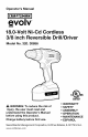
Operator's Manual II:RAFTSMANI evolv m 18.0-Volt Ni-Cd Cordless 3/8 inch Reversible Drill/Driver Model No. 320. 30856 c( us LISTED WARNING: To reduce the risk of injury, the user must read and understand the Operator's Manual before using this product. Charge battery before first use. Sears Brands Management www.oraftsman.oom Corporation, • • • • • • WARRANTY SAFETY ASSEMBLY OPERATION MAINTENANCE ESPAI_IOL Hoffman Estates, IL 60179 U.S.A.
I_ _I[I]ii [II_I__I Warranty page 2 Safety Symbols pages 3-4 Safety Instructions pages 5-10 Description pages 11-12 Assembly page 13 Operation pages 14-20 Maintenance pages 21-23 Troubleshooting page 24 Exploded pages 25-26 View and Part List CRAFTSMAN EVOLV ONE YEAR LIMITED WARRANTY FOR ONE YEAR from the date of purchase, this product is warranted against any defects in material or workmanship. With proof of purchase, a defective product will be replaced free of charge.
The purpose of safety symbols is to attract your attention to possible dangers. The safety symbols and the explanations with them deserve your careful attention and understanding. The symbol warnings do not, by themselves, eliminate any danger. The instructions and warnings they give are no substitutes for proper accident prevention measures.
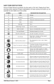
SAVE THESE INSTRUCTIONS Some of these following symbols may be used on this tool. Please study them and learn their meaning. Proper interpretation of these symbols will allow you to operate the tool better and more safely.
GENERAL _, POWER TOOL SAFETY WARNINGS WARNING: Read all safety warnings the warnings and instructions or serious personal injury. Save all warnings and instructions. Failure to follow listed below may result in electric shock, fire, and/ and instructions for future reference. The term "power tool" in all warnings listed below refers to corded or battery-operated (cordless) power tools. power tools WORK AREA SAFETY • Keep your work area clean and well lit.
PERSONAL SAFETY • Stay alert, watch what you are doing and use common sense when operating a power tool. Do not use the tool while tired or under the influence of drugs, alcohol, or medication. A moment of inattention while operating power tools may result in serious personal injury. • Use personal protective equipment. Always wear eye protection.
Keep cutting tools sharp and clean. Properly maintained cutting tools with sharp cutting edges are less likely to bind and are easier to control. Use the power tool, accessories, tool bits, etc., in accordance with these instructions, taking into account the working conditions and the work to be performed. Use of the power tool for operations different from those intended could result in a hazardous situation. BATTERY TOOL USE AND CARE • Recharge only with the charger specified by the manufacturer.
• Use auxiliary handle, if supplied personal injury. • Secure the workpiece. Clamping place better than the hand. • Always wait until the machine has come to a complete stop before placing it down. The tool insert can jam and lead to loss of control over the power tool. • Before performing any kind of work on the machine ( e. g. maintenance, tool change, etc) as well as when transporting and storing it, always set the rotational direction switch to the center position.
SAFETY RULES FOR POWER UNIT _1, WARNING: Read and understand all instructions. instructions listed below may result in electric personal injury. Failure to follow all shock, fire and/or serious Before using the power unit, read all instructions and cautionary markings in this manual, on the power unit, and the product using battery to prevent misuse of the products and possible injury or damage.
• Do not operate the power unit with a damaged cord or plug, which could cause shorting and electric shock, if damaged, have the cord and plug repaired or replaced by a qualified service technician. • Do not operate the power unit if it has received a sharp blow, been dropped or otherwise damaged in any way. Take it to a qualified service technician for an electrical check to determine if the power unit is in good working order. • Do not disassemble malfunctioning unit.
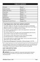
ID]=_.'_o_[[e_] KNOW YOUR CORDLESS DRILL/DRIVER (Fig. 1) Fig. 1 Two-speed Gearbox Switch Keyless Chuck Torque-Adjustment Ring Direction-of-Rotation Trigger Selector (Forward/ Center LocW Reverse) Worklight Battery-Release Button Power unit Plug ack PRODUCT SEPCIFICATIONS Motor 18.0 Volt DC No Load Speed LO 0-350/HI Chuck 3/8 inch Clutch 24 Positions Charging Weight (RPM) 5 -7 Hours time Drill/Driver 0-1300 (Without battery) 2.
_1, WARNING: The safe use of this product requires an understanding of the information on the tool and in this operator's manual, as well as knowledge of the project you are attempting. Before use of this product, familiarize yourself with all operating features and safety rules. ADJUSTABLE The drill/driver TWO-SPEED TORQUE has a 24-position clutch. GEAR BOX The two-speed gear box is designed for drilling or driving at LO or HI speeds.
_h, WARNING: If any parts are broken or missing, do not attach the battery pack to the drill/driver or operate the tool until the broken or missing parts are replaced. Failure to do so could result in possible serious injury. _, WARNING: Do not attempt to modify this drill/driver or create accessories not recommended for use with this drill/driver. Any such alteration or modification is misuse and could result in a hazardous condition leading to possible serious injury.
HOW TO CHARGE THE BATTERY PACK (Fig. 2} Detach the battery pack from the drill/driver. Insert the power unit jack into charging socket, making sure they are properly connected. Fig. 2 Power unit can be used with Charging socket normal house voltage of 120 volts, 60 Hz, AC only. Connect the plug of power unit to the electrical outlet. The indicator light on an battery pack shines red when the power unit is plugged into a power source. Charge the battery for at least 7 hours before the first use.
TO DETACH BATTERY PACK (Fig. 3} 1. Lock the trigger switch on the drill/driver by placing the direction-of-rotation (forward/center-lock/reverse) selector in center position. 2. Depress the battery release buttons to release the battery pack. 3. Pull forward A_, WARNING: condition. Therefore, (Fig .4) Fig. 4 Forward Reverse SPEED (Fig. 4) The variable-speed trigger switch delivers higher speed with increased trigger pressure and lower speed with decreased trigger pressure.
NOTICE: This drill/driver is equipped with an electric brake. When the brake is functioning properly, sparks may be visible through the vent slots in the housing. This is normal and results from the action of the brake. KEYLESS CHUCK Fig. 5 Keyless chuck OPEN (release) Chuckjaws Chuck body-- (Fig. 5) The drill/driver has a keyless chuck to tighten or release grip on the drill bits in the chuck jaws.
ADJUSTABLE-TORQUE CLUTCH The torque clutch can be adjusted to 24 different settings. The higher the torque setting, the more force the drill/driver produces to turn an object in either LO or HI rotation speed. When using the drill/driver for different driving applications, increase or decrease the torque appropriately help prevent damage to screw heads, threads, workpiece, etc. Adjust the torque torque-adjustment by rotating ring. the (Fig. 7) Fig.
LED WORKLIGHT (Fig. 9) The LED worklight, located on the base of the drill/driver, will illuminate when the trigger switch Fig. 9 ight is depressed. This provides additional light on the surface of the workpiece for operation in lower-light areas. The LED worklight will turn off when the trigger switch is released. INSTALLING BITS (Fig. 10) 1. Remove the battery. 2. Lock the trigger switch by placing the direction-ofrotation selector in the OFF (center) position. 3.
DRILLING (Fig. 12} Fig. 11 1. Check that the directionof-rotation selector is set to Forward. 2. Secure the material to be drilled in a vise or with Wrong! clamps to keep it from turning as the drill bit rotates. 3. Hold the drill/driver firmly, and place the bit at the point to be drilled. 4. Depress the trigger start the drill. switch to Move the drill/driver bit into 5. the workpiece, applying only enough pressure to keep the bit cutting.
METAL DRILLING For maximum performance, use high speed steel bits for metal or steel drilling. 1. When drilling metals, use light oil on the drill bit to keep it from overheating. The oil will prolong the life of the bit and increase the drilling action. 2. Begin drilling at a very low speed to prevent the bit from slipping off the starting point. 3. Maintain a speed and a pressure that will allow cutting the bit or drill/driver.
_, WARNING: When servicing, Fig. 13 use only identical replacement parts. Use of any other parts may create a hazard or cause product damage. GENERAL MAINTENANCE key-less chuck Mallet Avoid using solvents when cleaning plastic parts. Most plastics are susceptible to damage from various types of commercial solvents and may be damaged by their use. Use clean cloths to remove dirt, dust, oil, grease, etc.
4. Insert a 5/16 inch or larger hex key into the chuck of the drill/driver tighten the chuck jaws securely. 5. Tap the hex key sharply with a mallet in a clockwise loosen the screw in the chuck for easy removal. 6. Open the chuck jaws and remove the hex key. Using a screwdriver, the chuck screw by turning it in a clockwise direction. NOTICE: The chuck 7. screw has left-handed direction. and This will remove threads. Insert the hex key into the chuck and tighten the chuck jaws securely.
BATTERI ES: The battery pack is equipped with nickel-cadmium rechargeable batteries. The duration of use from each charge will depend on the type of work performed. The batteries in this tool have been designed to provide maximum troublefree life. Like all batteries, they will eventually wear out. Do not disassemble the battery pack or attempt to replace the batteries. Handling of the batteries, especially when wearing rings and jewelry could result in a serious burn.
PROBLEM The drill/driver work does not CAUSE SOLUTION Battery is depleted Charge the battery Bit cannot be installed Chuck is not open Open the chuck Motor overheating Be sure cooling vents are free from saw dust and obstacles Clean, clear vents.
1 3321267000 Left Housing Assembly 1 2 3700961000 Stop Spring 1 3 3126128000 Speed Change Button 1 4 2790267000 Motor and Gear Case Assembly 1 5 3126131000 Clutch Indicator 6 3126129000 Clutch 7 3123494000 Spring Holder 1 8 3704024000 Mounting 1 9 5610013000 Screw 13 10 3860086000 Chuck 1 11 5620179000 Screw (L.H.
I_[e]li_l 30856 Manual Revised 11-0623 Page 27
I_[e]li_l 30856 Manual Revised 11-0623 Page 28