® Assembly Operation Customer Responsibiiities Service and Adjustments ®Repair Parts CAUTION: Read and follow all safety FOR CONSUMER ASSISTANCE rules and instructions before operating HOT LINE, CALL THIS TOLL FREE NUMBER: this equipment° 1_800-659-5917
SAFETY RULES Practices for Ride-On Safe Operation Mowers IMPORTANT: THIS CUTTING MACHINE IS CAPABLE OF AMPUTATING HANDS AND FEET AND THROWING OBJECTS. FAILURE TO OBSERVE THE FOLLOWING SAFETY INSTRUCTIONS COULD RESULT IN SERIOUS INJURY OR DEATH.. I. • • • ° • • o ° ° • ° • • ° • II. GENERAL OPERATION Read, understand, and follow all instructions in the manual and on the machine before starting. Only allow responsible adults, who are famitiar with the instructions, to operate the machine.
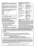
PRODUCT CONGRATULATIONS on your purchase of a Sears Tractor_ It has been designed, engineered and manufactured to give you the best possible dependability and performance._ Should you experience any problem you cannot easily remedy, please contact your nearest Sears Authorized Service Center/Department,. We have competent, welltrained technicians and the proper tools to service or repair this tractor,. Please read and retain this manual.
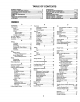
TABLE OF CONTENTS SAFETY RULES ............................................................ 2 PRODUCT SPECIFICATIONS ...................................... 3 CUSTOMER RESPONSIBILITIES ..................... 3, 17-21 WARRANTY .................................................................. 3 TABLE OF CONTENTS ................................................ 4 INDEX ............................................................................ 4 TRACTOR ACCESSORIES ..........................................
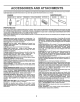
ACCESSORtES jjj iii/,l,J/u,,,i AND ATTACHMENTS II,,,,,,,I,,,,II,II,,HI,,, These accessories and attachments were available through most Sears retail outlets and service centers when the tractor was purchased.. Most Sears stores can order these items for you when you provide the model number of your tractor+ MAINTENANCE ENGINE SPARK PLUG GAS CAN ENGINEOIL FUELSTABILIZER AIR FILTER BLADES BELTS % PERFORMANCE Sears offersa wide variety of attachments that fityourtractor,.
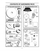
CONTENTS OF HARDWARE PACK _Ju,,llJ,,u,ll, Parts Bag contents shown full size i,llllllllllllllll ill u Parts packed separately in carton (1) Hex Boit 3/8-16 x I Seat Mulcher Steering Plate Boot (1) Large Flat Washer (1) Hex Bolt 5116-18 x 1-1/4 (!) Lockwasher 3/8 @ Steering Wheet (1) Locknut 5/16-18 Video Cassette (1) Hex Bolt 1/2-t3 x 1 r; Manual (1) Washer 17/32 x 1-3/16 x 12 Gauge Parts Bag Parts bag contents not shown full size (_x (2) Shoulder Bolts 7/8 x 14 Gauge (2) Centerlo
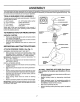
ASSEMBLY Your new tractor has been assembled at the factory with exception of those parts left unassembled for shipping purposes. To ensure safe and proper operation of yourtractoral! parts and hardware you assemble must be tightened securely_ Use the correct tools as necessary to insure ProPer tightness.
BLY CONNECT BAI"i'ERY (See Figs. 2 and 3) CAUTION: Do not short battery terminals. Before connecting battery, re- SEAT PAN bands, rings, etc. move metal bracelets, wristwatch Positive terminal must be connected first to prevent sparking from accidental grounding. uJl.i • Remove cardboard packing from seat pan and lift seat pan to raised posRion_ • Open battery box door. • Remove terminal protective caps and discard.
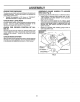
ASSEMBLY CHECK TIRE PRESSURE ASSEMBLE GAUGE DECK (See Fig. 5) The tires on your tractor were overinflatedat the factory for shipping purposes,, Correct tire pressure is important for best cutting performance° • Reduce tire pressure to PSi shown in "PRODUCT SPECIFICATIONS" on page 3 of this manual..
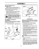
A INSTALL MULCHER LY PLATE DEFLECTOR SHIELD (See Figs. 6 & 7) - Install two latch hooks to mulcher plate using screw, washer, lock washer, and weld nut as shown.. NOTE; Pre-assemble weld nut to latch hook by inserting weld nut from the top with hook pointing down. • Tighten hardware securely. ° Raise and hold deflector' shield in upright position. = ° Place front of mulcher plate over' front of mower deck opening and slide into place, as shown. Hook front latch into hole on front of mower deck.
OPERATION These symbols may appear on your product or in literature supplied with the product. Learn and understand their meaning..
OPERATION KNOW YOUR TRACTOR READ THIS OWNER'S MANUAL AND SAFETY RULES BEFORE OPERATING YOUR TRACTOR Compare the illustrationswith yourtractor to familiarize yourself with the locations of various controls and adjustrnents_ Save this manual for future reference° LIGHT SWITCH IGNITION SWITCH POSITION AMMETER LIFT LEVER PLUNGER THROTTLFJCHOKE CONTROL ATTACHMENT LIFT LEVER © ATTACHMENT CLUTCH LEVER CLUTCHJBRAKE PEDAL PARKING BRAKE HEIGHT' ADJUSTMENT KNOB MOTION CONTROL LEVER APPROX SPEED 3 MPH 2 MPH
OPERATION The operation of any tractor can result in foreign objects thrown into the eyes, which can result in severe eye damage. Always wear safety glasses oreye shields while operating your tractor or performing any adjustments or repairs. We recommend a wide vision safety mask over the spectacles or standard safety glasses. HOW TO USE YOUR TRACTOR TO SET PARKING - Turn ignitionkey to "OFF" position and remove key.
OPERATION TO OPERATE IMPORTANT: THE MOTION CONTROL LEVER DOES NOT RETURN TO NEUTRAL (N) POSITION WHEN THE CLUTCHfBRAKE PEDAL IS DEPRESSED. • To restart movement, slowly release parking brake and clutch/brake pedal ° Slowly move motion control lever to slowest setting+ • Make all turns slowly.. MOWER (See Fig. 10) Your tractor is equipped with an operator presencesensing switch.
OPERATI ° The attachments can also be used during the engine warm-up period after the transmission has been warmed up° NOTE: If at a high altitude (above 3000 feet) or in cold temperatures (below 32 F) the carburetor fuel mixture may need to be adjusted for best engine performance. See "TO ADJUST CARBURETOR" in the Service and Adjustments section of this manual,.
OP MOWING TIPS MULCHING i Tire chains cannot be used when the mower housing is attached to tractor. • Mower should be properly leveled for best mow!,ng performance. See q'O LEVEL MOWER HOUSING in the Service and Adjustments section of this manual The left hand side of mower should be used for trimming. . MOWING TIPS IMPORTANT: FOR BEST PERFORMANCE, KEEP MOWER HOUSING FREE OF BUILT*UP GRASS AND TRASH.
CUSTOMER ' M_JNTE'NANCE RESPONSIBtL SCHEDULE AS YOUCOMPLETE REGULAR SERVICE ..... .,,_'___./__o_//_,,'f _'___O_,_=0_ €0"__"_._ ._" __.,_ _._ _ Check Tire Pressure _' JT 13'hock for Loose Fasteners _#t iR Sharpe_Replace T CheckBatteryLevel;Recharge " = ............... SERVICE i V' ................. _' .... _ Cooling N _2,3 '_ J_ .... _ Arrester Replace Oil Filter (If equipped) _.2 €ie_n EnginecoolinoFins _,'_= ........ v' Replace Air Filter Paper Cartridge v" .....
ill illlllllllllJllllllllJllllJllllJllllJllllllllllllllll ii iiilllJlllll illl ii ii illll i iJ iiii iiii i CUSTOMER i/ ii RESPONSIBILITIES TRACTOR TO SHARPEN Always observe safety rules when performing any maintenance. Care should be taken to keep the blade balanced, An unbalanced blade will cause excessive vibration and eventual damage to mower and engine. BRAKE OPERATION ° if tractor requires more than six (6) feet stopping distance at high speed in highest gear, then brake must be adjusted.
CUSTOMER RESPONSRBILmTIE$ BATTERY ENGINE Your tractor has a battery charging system which is sufficient for normal use° However, periodic charging of the battery with an automotive charger wit!extend its fife. LUBRICATION o Keep batter:/and terminals clean., , Keep battery bolts tight° ° o Keep smallvent holes open.
CUSTOMER AIR FILTER R BILITIES (See Fig. 18) CLEAN AIR SCREEN (See Fig. 19) Your engine will not run properly using a dirty air filter. Clean the foam pre-cleaner after every 25 hours of operation or every season_ Service paper cartridge every !00 hours of operation or every season, whichever occurs firsL Air screen must be kept free of dirt and chaff to prevent engine damage from overheating. Clean with awire brush or compressed air to remove dirt and stubborn dried gum fibers.
CUSTOMER RESPON JBULITIES MUFFLER CLAMP. inspect and replace corroded muffler and spark arrester (if equipped) as it could create a fire hazard and/or damage° CLAMP SPARK PLUGS Replace spark plugs at the beginning of each mowing season or after every 100 hours of operation, whichever occurs first. Spark plug type and gap setting are shown in "PRODUCT SPECIFICATIONS" on page 3 of this manual IN-LINE FUEL FILTER FU _EL___ FILTER " (See Fig. 20) FIG.
ICE AND ADJUSTMENTS i CAUTION: o o o i illl i ii illl illll illll i i ii illl BEFORE PERFORMING ANY SERVICE OR ADJUSTMENTS: Depress clutch/brake pedal fully and set parking brake. Place motion control lever in neutral (N) position. Place attachment clutch in "DISENGAGED" position° Turn ignition key "OFF" and remove key. Make sure the blades and all moving parts have completely stopped. Disconnect spark plug wire from spark plug and place wire where it cannot come in contact with plug.
SERVmCE AN TO LEVEL MOWER ADJUSTMENTS HOUSING FRONT-TO-BACK ADJUSTMENT (See Figs° 24 and 25) IMPORTANT: DECK MUST BE LEVEL SIDE-TO-SIDE IF THE FOLLOWING FRONT-TO-BACK ADJUSTMENT iS NECESSARY, BE SURETO ADJUST BOTH FRONT LINKS EQUALLY SO MOWER WILL STAY LEVEL SIDE-TOSIDE. TO obtain the best cutting results, the mower housing should be adjusted so that the front is approximately 1/4" to 3/4" lower than the rear when the mower is in its highest position° Check adjustment on right side of tractor.
AND ADJUSTMENTS TO REPLACE MOWER BLADE DRIVE WITH PARKING BELT BRAKE "ENGAGED" NUT "A" (See Fig. 26) NUT The mower blade drive belt may be replaced without tools° Park the tractor on level surface. Engage parking brake_ BELT REMOVAL= = Remove mower' from tractor (See "TO REMOVE MOWER" in this section of this manual). Work belt off both mandrel pulleys and idler pulleys_ ° Pull belt away from mower_ BELT INSTALLATION ° Install new belt in reverse order' of removal.
$ERVnCE AND ADJUSTMENTS TO ADJUST Fig. 29) MOTION CONTROL LEVER (See TO ADJUST STEERING if steering wheel crossbars are not horizontal (leftto right) when wheels are positionedstraight forward, remove steering wheel and reassemble per instructionsin the Assembly section of this manual..
i illll, IIIIL ii i i i iJ iiJ SERVICE AND ADJUSTMENTS TO REPLACE HEADLIGHT TO START ENGINE WiTH A WEAK BATTERY (See Fig. 31) CAUTION: Lead-acid batteries generate explosive gases. Keep sparks, flame and smoking materials away from bat_ teries. Always wear eye protection when around batteries. • • Raise hood_ Pull bulb holder out of the hole in the backside of the grill • Replace buib in holder and push bulb holder securely back into the hole in the backside of the grill.. Close hood.
SERVICE AND ADJUSTMENTS ENGINE FINAL SETTING - TO ADJUST THROTTLE (See Fig. 33) CONTROL - CABLE • The throttle control has been preset at the factory and adjustment should not be necessary° Check adjustment as described below before loosening cable. If adjustment is necessary, proceed as follows: o , With engine not running, move throttle control lever from slow (,_!) to choke (l\l) position_ Slowly move lever from choke (N) to fast (,_) position.
STORAGE immediately prepare your tractor for storage at the end of the season or if the tractor will not be used for 30 days or ENGINE more. FUEL SYSTEM TRACTOR IMPORTANT: IT IS IMPORTANT TO PREVENT GUM DEPOSITS FROM FORMING IN ESSENTIAL FUEL SYSTEM PARTS SUCHAS CARBURETOR, FUEL FILTER, FUEL HOSE, OR TANK DURING STORAGE.
u,JJ:Ji _l:::_ ............... TROUBLESHOOTmNG PROBLEM CAUSE Will not start 1 2, 3, 4, 5. 6. 7. Out of fuel Engine not "CHOKED" propedy=, Engineflooded Bad spark plug Dirty air filter_, Dirty fuel filter Water in fuel. 8 9 Loose or damaged wiring, Carburetor out of adjustment !0, Hard to start Engine will not turn over Engine clicks but will not start iuJJH,,llll,llii Loss of power POINTS CORRECTION 1, 2..
...... ,,, ,, , ,,, ................... TROUBLESHOOTING ................................. PROBLEM ........................................... POINTS i iiiiiiiiiiiiiiiii1[ CAUSE , ii[llU _"_ _'_ '_'T'_................. CORRECTION Engine continues to run when operator leaves seat with attachment clutch engaged 1, Faulty operatoPsafety presence control system 1, Check wtdng, switches and connections If not corrected, contact an authorized service cented department Poor cut- uneven 1_ 2.
TRACTOR - - MODEL NUMBER 917.259340 SCHEMATIC RED I BLACK BATTERY AMMETER I_R_ L| .... _ _I _--t_ I R_D_'_____ t l _-- _Gy Ak I CLUTCHI BRAKE 1 ...... ,I , -7-t--_7 (PEDALUP) ,,--, i _ , L.J-q- 1 SOLENOID ......... [ SEAT SWITCH (NOT OCCUPIED) ] -i .... I I I ! __ :z......_____J_ I--I _-z-4---_ ,-.z-i_ '_ _' , .............., .............. t k 7 ..... _CK 1" J >_z'_t _ ! c'-'_', -,-I! k_(.
REPAIR PARTS TRACTOR -- MODEL NUMBER 917.259340 ELECTRICAL 22 2t t l t 19 1 l _36 ) I / /t 1 .....
REPAaR PARTS TRACTOR - - MODEL NUMBER 917.259340 ELECTRICAL KEY NO.
REPAIR PARTS TRACTOR - - MODEL NUMBER 917.
REPAIR PARTS TRACTORCHASSIS - MODEL NUMBER 917.259340 AND ENCLOSURES KEY NO. PART NO.
REPAIR PARTS TRACTOR -- MODEL NUMBER 917.
REPARR PARTS TRACTOR - - MODEL NUMBER 917.259340 DRIVE KEY NOo 1 2 3 8 10 15 16 18 19 21 22 24 25 26 27 28 29 30 31 32 34 35 36 37 38 39 40 41 42 44 45 46 47 48 49 50 51 52 53 55 56 57 PART NO.
REPAIR PARTS TRACTOR -- MODEL NUMBER 917.259340 STEERING ASSEMBLY 7__--_,-_.._ 11 .,., __3__ _ , i ! I ' _-----_---" 42 62 ,,1 117 j18 20_ ,...1.1,_ 24/:j_'t" lCa-_ ""-.
REPABR PARTS TRACTOR STEERING - - MODEL NUMBER 917.259340 ASSEMBLY KEY NO.
REPAIR PARTS TRACTOR - - MODEL NUMBER 917.259340 SEAT ASSEMBLY 14 ,5 21 23 t2 KEY NO, 1 2 3 4 5 6 7 8 9 10 12 13 14 PART NO. 140123 t40551 STD523710 19131610 t 45OO6 STD5414.37 124181X 17490616 19131614 155925 121246X 12t248X 72050411 DESCRIPTION Seat Bracket, Pivot, Seat Bolt Washer 13/32 x ! x I0 Gauge Clip, Push-In Hinged Nut Spring, Seat Screw, Thd., Roll.
REPAUR PARTS TRACTOR - - MODEL NUMBER 917.259340 DECALS 23 2 6 3 t8 7 7 ! 9 5 18 10 4 I 11 8 22 13 12 13 14 17 KEY NO. 1 2 3 4 5 6 7 8 9 10 tl 12 PART NO, 140819 150333 151299 151300 149918 133644 150927 151302 146709 137537 4900J 146046 WHEELS DESCRIPTION KEY NO.
REPAIR PARTS TRACTOR - - MODEL NUMBER 917.
REPAIR PARTS TRACTOR - - MODEL NUMBER 917.259340 ENGINE KEY NO. PART NO.
REPAIR PARTS TRACTOR - - MODEL NUMBER 917.
REPAmRPARTS TRACTOR MOWER - - MODEL NUMBER 917.259340 LIFT KEY NO.
REPAIR PARTS TRACTOR -- MODEL NUMBER 917.259340 MOWER DECK 76 68 74 85_.
REPAgR PARTS TRACTOR -- MODEL NUMBER 9'17,259340 MOWER DECK KEY NO. PART NO.
REPAIR PARTS TRACTOR HYDRO GEAR TRANSAXLE -- MODEL NUMBER 917.
REPAIR PARTS TRACTOR HYDRO GEAR TRANSAXLE KEY PART NO. NO. 1 2 3 4 5 6 7 8 9 13 14 15 17 18 I9 23 24 25 26 27 28 29 34 35 36 37 38 39 40 41 142930 142931 142932 142928 142933 142934 142935 150771 142937 142938 142939 142940 142941 150772 150773 142944 142945 142946 150774 142948 142949 142950 142951 142952 142953 142954 142955 150777 150778 142958 - - MODEL NUMBER 917.
REPAIR PARTS TRACTOR BRIGGS & STRATTON ENGINE -- MODEL - MODEL NUMBER NUMBER 28N707, 917.259340 TYPE NUMBER 0173-01 230 3 P614 230 @ 634A 307 635 337 562 "k REQUIRES SPECIAL TOOLS TO INSTALL.
REPAIR PARTS TRACTOR-BRIGGS & STRATTON 127 138 MODEL NUMBER ENGINE - MODEL NUMBER 106 987 95 117 o@ 634 917.259340 28N707, TYPE NUMBER 0173-01 634B ++®® 52 '__ 5 + 137 121 CARBURETOR 142 104 147 1033 VALVE OVERHAUL OVERHAUL KIT 52 138_ 142 947 "_rREQUIRES SPECIAL TOOLS TO INSTALL. SEE REPAIR INSTRUCTION MANUAL.
REPAIR PARTS TRACTOR BRIGGS & STRATTON ENGINE 3 523 - - MODEL - MODEL 20 634A NUMBER NUMBER 842 917.
REPAUR PARTS TRACTOR - - MODEL NUMBER 917.
REPAIR PARTS TRACTOR BRIGGS & STRATTON KEY PART NO.
REPAIR PARTS TRACTOR BRIGGS & STRATTON KEY PART NO.
SERVICE N 56
SERVICE NOTES 58
SUGGESTED GUIDE FOR SiGHTiNG SLOPES FOR SAFE OPERATION ONLY RIDE UP AND DOWN HILL, NOT ACROSS HILL SIGHTING """-......CUT GUIDE SIGHT AND HOLD THIS LEVEL WITH SKY LINE OR TREE. O1 LO / 15 ° MAX. i i Jiiiii iiiiiiiiiiii_11J /I _1 /% _! AA _] O Operate your Tractor up and down the face of slopes (not greater than 15 ), never across the face. Make turns gradually to prevent tipping or loss of control. Exercise extreme _l,,, caution when changing direction on slopes.
[RRFTSMRN ® OWNER'S MANUAL 15.5 HP ELECTRIC START 42" MOWER AUTOMATIC (HYDROSTATIC) DRIVE LAWN TRACTOR MODEL NO. 917.259340 Each tractor has its own model number. Each engine has its own model number. The model number for your tractor will be found on the model plate located under the seat. The model number for your engine wilt be found on the blower housing of the engine. IF YOU NEED REPAIR SERVICE OR PARTS: All parts listed herein may be ordered from any Sears, Roebuck and Co.