SE_/ARS CRnFrZMnN MODEL NUMBER 917.
SAFETY RULES Safe Operation Practices for Ride-On Mowers IMPORTANTr THIS CUTTING MACHINE IS CAPABLE OF AMPUTATING HANDS AND FEET ANDTHROWtNG OBJECTS FAILURE TO OBSERVE THE FOLLOWING SAFETY INSTRUCTIONS COULD RESULT IN SERIOUS INJURY OR DEATH IIi. CHILDREN L GENERAL OPERATION i e a Read.
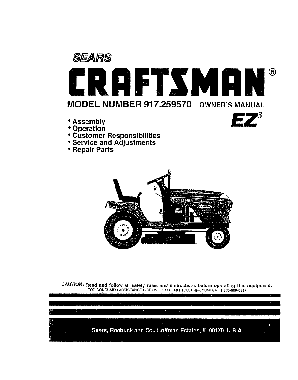
PRODUCT CONGRATULATIONS on your purchase of a Sears Tractor ff has been designed, engineered and manufactured to give you the best possible dependability and pedormance Shouid you experience any problem you cannol easiiy remedy, please contact your nearest Sears Authorized Service Center/Department Department, We have competent, welt-tralned techniciansand the proper toolsto service or repair this tractor.. Please read and retain this manual.
TABLE OF CONTENTS SAFETY RULES ............................................................ 2 PRODUCT SPECIFICATIONS ........................................ ',. 3 CUSTOMER RESPONSIBILITIES .,°o._............... 3, 17'-20 WARRANTY ................................................................. 3 'TABLE OF CONTENTS ............................................... 4 INDEX ............................................................................ 4 TRACTOR ACCESSORIES .....................................
ACCESSORIES AND ATTACHMENTS These accessoriesend attachmentswereavailable through most Sears retatloutlets end service centers when Ihe tractor was purchased Moat Sears stores can order these iiems for you when you provide the model number of your Iractor_ ENGINE SPARKPLUG MAINTENANCE GAS CAN ENGINEOIL FUELSTABILIZER AIR FILTER BLADES BELTS % PERFORMANCE Sears criers a wide vadety of altachments Ihaffityour Iracior Many el these are listed below with br{el explanations el how they can harp you.
CONTENTS OF HARDWARE PACK i i Parts packed separately in carton Seat Video Casselte Steedng Wheel (1) Shoulder Bolt 5/16-18 (1) Hex Bolt 112-13 x 1 Pads Bag (1) Washer 17/32 x 1-3/16x 12 Gauge Lock 1/2 ..{2)-Washers=3!8 (2) Shoulder .............
ASSEMBLY Your new tractor has been assembled at ihe factory with exception of these parts left unassembled for shtpping purposes, To ensure safe and proper operation of your tractor afl parts and hardware you assemble must be tightened securely. Use the correct tools as necessary to insure proper tightness TOOLS REQUIRED FOR ASSEMBLY A socket wrench set wtfl make assembly easier.
ASSEMBLY i i ml ii ,inll,n,mnllllu i i t U HOW TO SET UP YOUR TRACTOR illl Ill INSTALL SEAT (See Fig. 3) Adjust seat before tightening CONNECT BATTERY (See Fig. 2) CAUTION: Do not short battery terminals by allowing a wrench or any other object to contact both terminals at the samettme. Before connecting battery, remove metal bracelets, wristwatch bands, rings, etc. Positive terminal must be 5onnected flrstto prevent sparking from acciden_ ta! grounding, • Lilt hood to raised position.
ASSEMBLY ASSEMBLE GAUGE WHEELS TO MOWER DECK (See Fig. 4) TO CONVERT TO BAGGING OR DISCHARGING The gauge wheels are designed to keep the mower deck In proper position when operating mower Be sure they are properly adjusted to ensure optimum mower performance, Simply remove mulcher plate and store in a safe place, Your mower Is now ready for discharging or installalton of optionaI grass catcher accessory.
i ASSEMBLY ,/CHECKLIST BEFORE YOU OPERATE AND ENJOY YOUR NEW TRA CTOR, WE WISH TO ASSURE THAT YOU RECEIVE THEBES T PERFORMANCE AND SA TISFA C TION FROM THIS QUALITY PRODUCT. PLEASE REVIEW THE FOLLOWING instructions CHECKLIST." ,." All assembly have been completed, / No remaining loose paris in cation, v" Batteryis properly prepared and charged_ 1 hour at 6 amps).. ' (Minimum ,/" Beat is adjusted comfodably €" All tires are properly Inflated.
u,u ,un u i u uu uulnllll i i OPERATION ,ipllJ,umHn i i in i i These symbols may appear on your tractor or in (I1erature supplied with the product.
KNOW YOUR TRACTOR READ THIS OWNER'S MANUAL AND SAFETY RULES BEFORE OPERATING YOUR TRACTOR Compare the {tlustratlons with your tractor to famlffarize yourself with the locations of va rlous controls and adjustments, this manual for future reference. Save LIGHT CHOKE CONTROL AMMETER ATTACHMENT CLUTCH LEVER SWITCH POSITION THROTTLE CONTROL _-_ ATTACHMENT LtFT LEVER © CLUTCH/ PEDAL HEIGHT ADJUSTMENT KNOB PARKING BRAKE FREEWHEEL CONTROL MOTION CONTROL LEVER -,APPRGX, SPEED 3 MPH 2MPH 1MPH FIG.
OPERATION l In severe eye damage. Always wear safety glasses or eye shlelds while operating your tractor or performing any adjustments or repairs° We recommend a wide vision safety mask over the The operation of any tractor can result in foreign objects thrown into the eyes, which can result spectacles or Standard safety glasses. _ , 11 .........
OPERATION TO OPERATE MOWER (See Fig. 9) Your tractor isequipped with an operatorpresence sensing switch Any attempt by the operator to leave the seat with the engine running and the attachment clutch engaged witI shut off the englne_ • Select desired height of cut.
OPERATION ..i .H.,I WARNtNO: Expe,enoe indtcaie ihata co ol' b e'nd n I I I I . Be sure the tractor ts on level ground_ Place the motion control lever in neutral. Release the parking brake and Iet the clutch?arake slowly return to operallng position, • Allow one minute for transmtsslon to warm up.
OPERATION i,J,,,,,,, ,,, i, i ii iii i MOWING ::::::::::::::::::::::: TIPS ii i ,,,,i ,, ,Hll MULCHING MOWING TIPS • Tire chains cannot be used when the mower housing is attached to tractor. IMPORTANT= FOR BEST PERFORMANCE, KEEP MOWER HOUSING FREE OF {3UfLT-UP GRASS AND TRASH CLEAN AFTER EACH USE. • Mower should be propedy levered for best mowing performance. See 'TO LEVEL MOWER HOUSING"in the Service and Adjustments section of this manual.
CUSTOMER RESPONSIBILITIES l_Ch_ng_mot_ oIi_r_whonoO_r_((ng _n_or a h_o_ I_d or t_ h)ghamb_o_l t_r_pQ_lvr_ll e _ S_l.Vt_morooI(_t__h_ll oper_t_r_Ir_dirty o_d_f_Iy¢_ndiIIot_ 3. I! oqulpp_dwilhoil (I)_or, _h[_eo o_owty 50 hours 4 .. Rep!scebladesm_e oi|enwhentoo, ,_ fn _ndy so(L GENERAL RECOMMENDATIONS LUBRICATION CHART The warrartty on this tractor does not cover items that have been subjected to operator abuse or negligence..
nl i II ,,i, CUSTOMER RESPONSIBILITIES ,U,l,i ,in i i I I TRACTOR TO SHARPEN BLADE (See Fig. 14) Always observe safety rules when performing any maintenance Care should be taken to keep the blade balanced An unbalanced blade will cause excessive vibration and evem tuaI damage 1o mower and engine BRAKE • The blade can be sharpened with a file or on a gdndhg wheel. Do not attempt to sharpen while on the mower.
CUSTOMER RESPONSIBILITIES V_BELTS • Check V-bottsfor dote riorattonand wear after 100 hoursof operation and replace if necessary The botts are not adjustable Replace belts If they begin to slip from wear, After ot{has drained completely, replace ofl drain plug and tighten securely " Reffil engine with oil Ihrough otF ftl! dipstick lube, Pour s_owly. Do not overfill, Forapp_x_mate capacity see PRODUCT SPECIFICATIONS on page 3 of this manual • Use gauge on oil fill cap/dipstick for checking level.
CUSTOMER RESPONSIBILITIES = 11 H.HHH ,HN= MUFFLER iMPORTANT: PETROLEUM SOLVENTS, SUCH AS KEROSENE, ARE NOT TO BE USED TO CLEAN THE CARTRtDGE_ THEY MAY CAUSE DETERIORATION OF THE CARTRIDGE.
SERVICE AND ADJUSTMENTS ,,, ,,,,,,, ii i, iiiiii1,111,1, i • , ii iii CAUTION: _i • • i i ,,,i BEFORE PERFORMING ANY SERVICE _L ,111 iiriii ii OR ADJUSTMENTS; Place motion control lever in neutral (N) position, Depress clutch/brake pedal fully and set parking brake. Place attachment clutch in "DISENGAGED" posit|on. Turn ignition key "OFF" and remove key. Make sure the blades and al,i moving parts have completely stopped.
SERVICE AND ADJUSTMENTS i ,,,,,,,,,,, i, t, ,, nm 11111 ii ,1,, n Adjust the mower while tractor ls parked on level ground or driveway Make sure tires are properly inflated (See "PRODUCT SPECIFICATIONS" on page 3 of th s manual), tf tires are over or underinflated, you will not properly adjust FRONT-TO-BACK ADJUSTMENT (See Figs, 23 and 24) IMPORTANT: DECK MUST BE LEVEL SIDE-TO-SIDE, IF THE FOLLOWING FRONT.
SERVICE AND ADJUSTMENTS TO REPLACE (See Fig. 25) MOWER BLADE DRIVE BELT TO ADJUST BRAKE (See Fig. 26) Your tractor }s equipped with an adjustable brake system which is mounted on the side of the transaxle The mower blade drive belt may be replaced without tools Park the tractor on level surface Engage parking brake BELT REMOVAL - If tractor requtres more than six (6) feet stopping distance at high speed in highest gear, then brake must be adjusted. , • Depressclutchforakepedalandengageparkingbrake.
SERVICE AND ADJUSTMENTS TO REPLACE MOTION DRIVE BEt.T (See Fig. 27) TO ADJUST MOTION CONTROL LEVER (See Fig. 28) Park the tractor on level surface. Engage parking brake For assistance, there is a belt lnstatlatic, n guide decal on botlom side of reft footrest The motion controt lever has been preset at the factor'] and adjustment should not be necessary , Remove mower (See "TO REMOVE MOWER" In this section of Ibis manual.
,, ,,,, ,L LLIL , I SERVICE AND ADJUSTMENTS • TO ADJUST STEERING WHEEL ,JiJ.,. i , JI.L IL TO START ENGINE WITH A WEAK BATrERY (See Fig. 30) ALIGNMENT If Steedng wheel crossbars ar e not hodz0ntal (Ie!t to right) when wheels are positioned siralght forward, remove steering wheel and reassemble perlnstrucflons In the Assembly section of this manual., J_IU U_ LLLL ateexploslvegaseso Keepsparks,flame and smoking materials away from batteries.
SERVICE AND ADJUSTMENTS illlll TO REPLACE . • Raise hood Putt bulb holder out of the hole in the backside of the gdlt Reptace bulb In hoider and push bulb holder securely back !nto the he e in the backside of the gdtL Close hood, • . HEADLIGHT llllll i ill i ENGINE BULB TO ADJUST THROTTLE CONTROL CABLE (See Fig.
i ii i ii ii iiii iiiiiiiiiiiiiiiiiiiiihllllll SERVICE AND ADJUSTMENTS [HJHHH TO ADJUST CHOKE CONTROL (See Fig. 33) The choke control has been preset at the factory and adjustment should not be necessary. Check adjustment as described beiow before loosening cable. If adjustment is necessary, proceed as follows: = With engine not running, move choke control (located on dash panel) to full choke (I\l) position.
Ji un i ................. STORAGE ENGINE immediately prepare your tractor for storage at the end of the season or if the traclor will not be used for 30 days or more. FUEL SYSTEM iMPORTANT: tT IS IMPORTANT TO PREVENT GUM DEPOSITS FROM FORMING IN ESSENTIAL FUEL SYSTEM PARTS SUCH AS CARBURETOR, FUEL FILTER, FUEL HOSE, OR TANK DURING STORAGE.
TROUBLESHOOTING JJu,,,,,,, , =,, PROBLEM =, POINTS ,,,,,H,H, H ,,= L CAUSE HH_,,H,H,, CORRECTION =, Wgl not start 1 2 3 4 5 6 7, Out of fuel Engine nat =CHOKED" prepetty Engine flooded Bad sparkpfug Dirty air titter Dirty fuel filter Wafer tn fuel 1 2. 3 4 5 6 7 B g_ Loses or damaged widng Carburatar out at adtus!ment 8 9 10 Hard to start Engfne wlfl not turn Engine vefvsa out of adjuslment t0 I. 2 3 4 5.
TROUBLESHOOTING PROBLEM Engine continues to run when operator leaves Seat with attachment clutch engaged ' CAUSE l, i,n poor_ul_uneveN Mower blades wig not rotate Poor grasa discharge POINTS CORRECTION Faultyoperator,safety presencecenirolsyslem ,,/ ii , Check wiring, swltchas and connections If not corrected, contact an eulhorlzod service cenlerl dspadmenl • I 2 3 4.
TRACTOR - - MODEL NUMBER 917.
REPAIR PARTS TRACTOR - - MODEL NUMBER ELECTRICAL 26 25 12 7 32 9i7.
REPAIR PARTS TRACTOR - - MODEL NUMBER 9'17.259570 ELECTRICAL KEY NO. PART NO.
REPAIR PARTS TRACTOR - - MODEL NUMBER 917;259570 CHASSIS AND ENCLOSURES 53 14 37 54 3 14 3 34
REPAIR PARTS TRACTOR -" MODEL NUMBER 9'17.259570 CHASSIS AND ENCLOSURES KEY NOr PART NO. 1 2 3 159527 159527 17490612 4 5 9 10 11 t2 13 14 STD551025 155272 150156X011 STD533710 155927 145660 155938 17490608 17 18 20 23 25 26 144983X558 126938X 156437 124028X 19131312 STD541437 28 29 30 31 37 38 145t98X558 155217 15t287X556 139976 174905o8 139886 39 139887 51 62 53 54 73800400 19091416 145201 17030814 55 145202 57 STD552507 58 140547 60 72140606 64 154796 71 73680400 74 STD5414.
REPAIR DRIVE PARTS TRACTOR - - MODEL NUMBER 9'17.
REPAIR PARTS TRACTOR, - MODEL NUMBER 917.259570 DRIVE KEY NO, l 2 3 8 10 15 16 18 19 21 22 24 25 26 27 28 29 30 32 34 35 36 37 38 39 40 41 42 47 49 49.. 50 51 52 53 55 56 57 59 61 62 PART NO, 15007! 142431 143995 154792 STD561210 74490544 STD54143I STD523710 $3D541437 130564 145627 73350600 106888X STD55t037 STD561210 145204 124236X 130807 74760512 155071 120!83X 19211616 1572H 123674X STD523727 4470J 154777 19131312 127783 154604 123205X ....
REPAIR PARTS TRACTOR -- MODEL STEERING ASSEMBLY L j , | , , i I 62 38 NUMBER 917.
REPAIR PAH 15 TRACTOR - - MODEL NUMBER 917.
REPAIR PARTS TRACTOR -- MODEL NUMBER 917.
REPAIR PARTS TRACTOR - - MODEL NUMBER 917.259570 ENGINE KEY NO, 1 2 4 5 6 7 8 10 11 12 13 14 15 15 17 23 25 26 27 29 31 32 33 34 35 37 36 PART NO, 151273 17720410 t49723 144O69 t44066 138129 150176 145552 STD55!125 STD522507 272250 13280338 132O0300 STD55!237 17490624 156123 145996 73920600 152927 _37160 157103 155971 123487X 108082X 17490512 8543R ........ -39 ..109227X ......
REPAIR PARTS TRACTOR -- MODEL NUMBER 917.
REPAIR PARTS TRACTOR - - MODEL NUMBER 917.259570 MOWER LIFT KEY NOo PART NO. DESCRIPTION 1 159460 Wire Assy., Inner/Spring, w/Plunger 2 159471 Shaft Asm. Lift 3 105767X Pin Groove 4 12000002 E Ring ,/'/5133-62 5 19211621 Washer 21/32 x 1 x 21 Ga.
REPAIR PARTS TRACTOR - - MODEL NUMBER 917.259570 MOWER DECK 76 37 _ 84 34 .
REPAIR PARTS TRACTOR -- MODEL NUMBER 917.259570 MOWER DECK KEY Nee PART NO. 1 2 3 4 5 6 8 9 10 1! 12 13 144393 STD533107 138017 138440 STD624008 130832 850657 STD551137 149296 134149 129895 137645 14 128774 15 110485X 16 140329 17 72110610 18 72140505 19 132827 20 136888 2t STD54143I 22 134753 23 131267 24 108304X 25 123713X 26 110452X 27 130968 28 19111016 29 131491 30 138776 .......... 31.
REPAIR PARTS TRACTOR - - MODEL NUMBER 917.
REPAIR PARTS TRACTOR - - MODEL NUMBER 917.259570 DECALS 17 22 19 14 13 14 5 I KEY' NO. PART NO, KEY NO.
REPAIR PARTS TRACTOR - - MODEL NUMBER 917.
REPAIR PARTS TRACTOR - - MODEL NUMBER 917.259570 HYDRO GEAR TRANSAXLE - MODEL NUMBER 310-0650 KEY PART NO. NO.
REPAIR PARTS TRACTOR - - MODEL NUMBER 917.
REPAIR PARTS TRACTOR-- MODEL NUMBER 917.259570 BRIGGS & STRATTON ENGINE - MODEL NUMBER 42E707, TYPE NUMBER 1631-01 51 L358 GASKET SET ] 51A 5! IB61 PUMP REPA!,R,,,KIT _ _"-_ _1o2 "" 95 ]_104 52 , 103 257 ,,3_"_ _ _,%32.32 _, m-37 f...... - -.._.
REPAIR PARTS TRACTOR - - MODEL NUMBER 9'17.
REPAIR PARTS TRACTOR - - MODEL NUMBER 917.259570 BRIGGS & STRATTON ENGINE - MODEL NUMBER 42E707, TYPE NUMBER 1631-01 o 9 8A 9 244 572 5A !0A 13 [1058 OWNER'S MANUAL t 110t9 LABEL KITt '_ REQUIRES SPECIAL TOOLS TO INSTALL, SEE REPAIR INSTRUCTION MANUAL.
REPAIR PARTS TRACTOR - - MODEL NUMBER 917.259570 BRIGGS & STRA'I-I'ON ENGINE - MODEL NUMBER 42E707_ TYPE NUMBER 1631-01 KEY PART NO. NO.
REPAIR PARTS TRACTOR -_- MODEL NUMBER 917.259570 BR|GGS & STRATTON ENGINE - MODEL NUMBER 42E707, TYPE NUMBER 1631-01 KEY PART NO. NO. 227491297 22962199 230223882 235224995 240394358 244230318 25793897 25894623 259223890 266221535 26794906 28494674 284A 94882 304 495469 305 94786 306 222846 306A 223734 307 94930 308 224774 308A 224775 309 497596 31094003 311497608 332230674 333394891 33494731 337802692 356494705 358491856 36319203 38389838 387280197 _92 2e!P95 KEY PART NO, NO.
SERVICE NOTES 56
....... _................ i_ ¸ " - ............. _ .... , _ _ SERVICE NOTES 57 _ : • .:..:... • ........
_ - _ HHHNIIH_ IIH]ll IH Ill _ I I I . .
SUGGESTED I GUIDE FO_ SIGHTING SLOPES FOR SAFE OPERATION ONLY RIDE UP AND DOWN HILL, NOT ACROSS HILL "" SIGHTING SIGHT AND HOLD THIS LEVEL WITH SKY LINE OR TREE. 15 ° MAX. _i A _1 Al, i_ _ _| Operate you_Tractor up and down the face of slopes (not greater than _15°),never across the face. Make turns gradually to prever_t tipping or loss of control. Exercise extreme caution wher_ changing direction on slopes.
£RAFTSMnN® OWNER'S MANUAL 19.5 HP ELECTRIC START 42" MOWER AUTOMATIC (HYDROSTATIC) LAWN TRACTOR MODEL NO. 917.