Owr_er's Manual (RAFTSMRNo 19.5 HP ELECTRIC START 42" MOWER 6 SPEED TRANSAXLE LAWN TRACTOR Model No. 917.270812 ° • ° • Safety Assembly Operation Maintenance • Repair Parts CAUTION: For answers to your questions about this product, Call: Read and follow all Safety Rules and Instructions before operating this equipment. 1-800-659-5917 Sears Craftsman Help Line 5 am - 5 pro, Mon- Sat Sears, Roebuck and Co., Hoffman Estates, IL 60179 Visit our Craftsman website: www.sears.
Maintenance ......................................... 18 Service and Adjustments ...................... 22 Storage ................................................. 28 Troubleshooting .................................... 29 Repair Parts ......................................... 34 Parts Ordering ....................... Back Cover Warranty ........................... :..................... 2 Safety Rules ..................... :..................... 2 Product Specifications ...........................
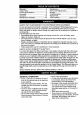
Turn off bladeswhen not mowing. Stop enginebeforeremovinggrass catcheror uncloggingchute. Mow onlyin daylightor good artificial light. Do not operatethe machinewhileunder the influenceof alcoholor drugs. Watchfor trafficwhen operatingnearor crossingroadways. Use extracare when loadingor unloadingthe machineinto a traileror truck. 3LOPE OPERATION • Do nottry to stabilize the machine by putting your foot on:the ground. • Do not use grass catcher on steep slopes.
• Never make adjustments or repairs with the engine running. • Grass catcher components are subject to wear, damage, and deterioration, which could expose moving parts or allow objects to be thrown. Frequently check components and replace with • Be sure the area is clear of other people before mowing. Stop machine if anyone enters the area. • Never carry passengers. • Do not mow in reverse unless absolutely necessary. Always look down and behind before and while backing. • Never carry children.
PRODUCT SPECIFICATIONS Should you expenence any problem you cannot easily remedy, please contact you_ nearest Se&rs Authorized Service Center. GASOLINE CAPACITY AND TYPE' 3.5 GALLONS UNLEADED REGULAR 'OIL TYPE SAE 30 (above 32°F) API-SF/SG/SH): SAE 5W-30 (below 32°F) instructions wdl enable you to assemble and maintam your tractor properly. Always observe the "SAFETY RULES". OIL CAPACITY: 3.0 PINTS SPARK PLUG: GAP: .030") Champton J19LM VALVE CLEARANCE: INTAKE: .004"-.006" EXHAUST: .007"-.
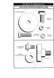
PARTS BAG CONTENTS SHOWN FULL SIZE (1) Large Flat Washer (1) Hex Bolt 3/8-16 x 1 (1) Lockwasher 3/8 (1) Hex Bolt 5/16-18x 1-1/4 (1) Locknut 5/16-18 (1) Shoulder Bolt 5/16-18 (1) Washer 17/32 x 1-3/16 x 12 Gauge © (1) Knob 6
PARTS BAG CONTENTS SHOWN FULL SIZE #10x5/8 Washers # t 0 (2) Lock (2) Screws (2) Weld Nuts _ I #10 (2) Washers 3/16 x 314 x "_6Gauge Parts packet separately in carton Parts Bag contents not shown full size Steering Wheel Adapter N; Seat Steering Wheel Insert Video Cassette f--"_.
Yournewtractorhas beenassembledat the factorywith exceptionof thoseparts left unassembledfor shippingpurposes.Toensuresafe andproperoperationof your tractor all partsand hardwareyou assemblemustbe tightenedsecurely.Usethe correcttools as necessaryto insure propertightness.Reviewthe video cassettebeforeyou begin. TOOLS REQUIRED ASSEMBLY FOR A socket wrench set will make assembly easier. Standard wrench sizes you need are listed below.
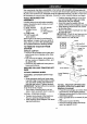
HOW TO SET UP YOUR TRACTOR CONNECT BATTERY • Lift hood to raised position. • If this battery is put into service after month and year indicated on label (label located between terminals) charge battery for minimum of one hour at 6-10 amps. (See "BATTERY" in MAINTENANCE section of this manual for charging .-.. instructions). :* : • / *'5" :.... ........I INSTALL /Label I INSTALL MULCHER PLATE • Install two latch hooks to mulcher plate using screw, washer, lock washer, and weld nut as shown.
TO CONVERTTO BAGGINGOR DISCHARGING Simplyremove mulcher plate and store in a safe place. Your mower is now ready for discharging or installation of optional grass catcher accessory. NOTE: It is not necessary to change blades. The mulcher blades are designed for discharging and bagging also, CHECK TIRE PRESSURE The tires on your tractor were overinflated at the factory for shipping purposes. Correct tire pressure is important for best cutting performance.
Thesesymbolsmay appearon yourtractoror in literaturesuppliedwith the product. Learnand understand their meaning.
KNOW YOUR TRACTOR READ THIS OWNER'S TRACTOR MANUAL AND SAFETY RULES BEFORE OPERATING YOUR Compare the illustrations with your tractor to familiarize yourself with the locations of various controls and adjustments. Save this manual for future reference. Light Attachment Clutch Lever Ammeter Switch Choke Contr ..
The operation of any tractor can result in foreign objects thrown into the eyes, which can result in severe eye damage. Always wear safety glasses or eye shields while operating your tractor or performing any adjustments or repairs. We recommend a wide vision safety mask over spectacles, or standard safety glasses. HOW TO USE YOUR TRACTOR Your tractor is equipped with an operator presence sensing switch.
TO AI_'JUST MOWER CUTTING HEIGHT The cL]tting height is controlled by turning the height adjustment knob in desired direction. • Turn knob clockwise (G) to raise cutting height. • Turn knob counterclockwise (O)to lower cutting height. The cutting height range is approximately 1-1/2" to 4". The heights are measured from the ground to the blade tip with the engine not running. These heights are approximate and may vary depending upon soil conditions, height of grass and types of grass being mowed.
ADD GASOLINE TO TRANSPORT • Raise attachn_ent lift to highest with attachment lift control. position • When pushing or towing your tractor, be sure gearshift lever is in neutral (N) position. • Do not push or tow tractor at more than five (5) MPH. NOTE: To protect hood from damage when transporting your tractor on a truck or a trailer, be sure hood is closed and secured to tractor. Use an appropriate means of tying hood to tractor (rope, cord, etc.).
TO START ENGINE ; When starting the engine!for the first time COLD WEATHER BELOW) " or if the engine has run out of fuel, it will take extra cranking time to move fuel from the tank to the engine. • Sit on seat in operating:position, depress clutch/brake pedal and set parking brake. • Place gear shift lever in neutral (N) position. • Move attachment clutch to "DISEN- • When engine starts, slowly push choke control in until the engine begins to run smoothly.
MOWING TIPS • Tire chains cannot be used v_hen the mower housing is attached t6 tractor. • Mower should be properly leveled for best mowing performance. See "TO LEVEL MOWER HOUSING" in the Service and Adjustments section of this manual. • The left hand side of mower should be used for trimming. • Drive so that clippings are discharged onto the area that has been cut. Have the cut area to the right of the machine. This will result in a more even distribution of clippings and more uniform cutting.
CUSTOMER RESPONSIBILITIES MAINTENANCE SCHEDULE _'_'__ AS *OU COMPLETE REOO LA°SE RV,CE ._o_ _ _°_'/ " ion T R Check Operator Presence Interlock Systems Check for Loose Fasteners O Sharpen/Replace Mower Lubrication Chart Check Battery Level R Clean T Battery Adjust Blade tl_7 Blades _4 V p Motion Check Engine V' Tension Drive Belt(s) V's Tension V'5 Oil Level Engine V' If Oil _.
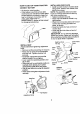
TRACTOR Always observe safety rules when performing any maintenance. BRAKE OPERATION If tractor requires more than six (6) feet stopping distance at high speed in highest gear, then brake must be adjusted. (See "TO ADJUST BRAKE" in the Service and Adjustments section of this manual). TIRES IMPORTAI_T: To ensure proper assembly, center h_le isn blade must align with star on mandrel assembly. • Reassemble hex bolt, lock washer and; flat washer in exact order as shown. • Tighten _olt securely (27-35 Ft.
• Keep battery and terminals clean. • Keep battery bolts tight. • Keep small vent holes open. • Recharge at 6-10 amperes for 1 hour. NOTE: The original equipment battery on your tractor is maintenance free. Do not attempt to open or remove caps or covers. Adding or checking level of electrolyte is not necessary. TO CLEAN BATTERY AND TERMINALS Corrosion and dirt on the battery and terminals can cause the battery to "leak" power. • Remove terminal guard.
• Saturate it in engine oil. Wrap it in clean, absorbent cloth and squeeze remove excess oil. • If very dirty or damaged, cleaner. replace to • Remove wing nuts and cartridge plate. • Carefully remove cartridge to prevent debris from entering carburetor. • Clean cartridge by tapping gently on flat surface. If very dirty or damaged, replace cartridge. • Reinstall cartridge plate, wing nuts, precleaner, cover and secure with knob(s).
_,CAUTION: Beforeperformingany serviceor adjustments: • • • • • • Depress clutch/brake pedal fully and set parking brake. Place gearshift lever in neutral (N) position. Place attachment clutch in "DISENGAGED" position. Turn ignition key "OFF" and remove key. Make sure the blades and all moving parts have completely stopped. Disconnect spark plug wire from spark plug and place wire where it cannot come in contact with plug. TRACTOR • Disconnect front links from deck by removing retainer springs.
TO LEVEL MOWER HOUSING Adjust the mower while tractor is parked on level ground or driveway. Make sure tires are properly inflated (See "PRODUCT SPECIFICATIONS" section of this equal in length. Both links should be approximately 10-3/8". • If links are not equal in length, adjust one link to same length as other link. • To lower front of mower loosen nut "E" manual). If tires are over or underinflated, you will not properly adjust your mower. on both front links an equal number of turns.
BELTINSTALLATION• Installnewbelt in reverseorderof removal. • Makesure belt is in all pulleygrooves and insideall beltguides. • Installmowerin reverseorderof removalinstructions. Mandrel Pulle_ TO REPLACE MOTION DRIVE BELT Park the tractor on level surface. Engage parking brake. For assistance, there is a belt installation guide decal on bottom side of left footrest. • Remove mower (See "TO REMOVE MOWER" in this section of this manual.) • Remove belt from stationary idler and clutching idler.
Gearshift Lever Neutral Lock Gate ,;_ Adjustment Bolt TO ADJUST MENT STEERING WHEEL ALIGN- If steering wheel crossbars are not horizontal (left to right) when wheels are positioned straight forward, remove steering wheel and reassemble per instructions in the Assembly section of this manual. FRONT WHEEL TOE-IN/CAMBER The front wheel toe-in and camber are not adjustable on your tractor.
REPLACING BATTERY TO REPLACE FUSE Replace with 30 amp automotive-type plug-in fuse. The fuse holder is located behind the dash. ,&,CAUTION: Do not short battery terminals by allowing a wrench or any other object to contact both terminals at the same time. Before connecting battery, remove metal bracelets, wristwatch TO REMOVE HOOD AND GRILL ASSEMBLY • Raise hood. bands,rings,etc. Positive terminal must be connected first • Unsnap headlight wire connector. • Stand in front of tractor.
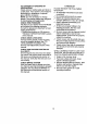
• Removeair cleaner cover, filter and cartridge plate to expose carburetor choke (see "AIR FILTER" in the Maintenance section of this manual). • Choke should be closed. If it is not, loosen casing clamp screw and move choke cable until choke is completely closed. Tighten casing clamp screw securely. • Reassemble air cleaner. Clamp Screw_ Quarter_=_.._,_._ _Circle _ _ *_>_ _ __'l'_._""-- ] f Swive I Choke FINAL SETTING - • Start engine and allow to warm for five minutes.
Immediatelyprepareyourtractorfor storage at the endof the seasonor if-thetractor_willnot be usedfor 30 daysor more. _,CAUTION: Neverstorethe tractorwith gasolinein the tank insidea building wherefumes mayreachan openflameor spark.Allowthe engineto coolbeforestoring in any enclosure. TRACTOR Remove mower from tractor for winter storage. This will allow you to clean it thoroughly. Remove all dirt, grease, leaves, etc. Store in a clean, dry area.
CHART TROUBLESHOOTING i PROBLEM CAUSE Will not start • Outoffuel. CORRECTION _ • Engine not"CHOKED" properly. • Engine flooded. • Bad spark plug. • Loose or damaged wiring. • Carburetor out of adjustment. • • • • • • • • • • • Engine valves out of adjustment. over • Clutch/brake pedal not depressed. • Attachment clutch is engaged. • Weak or dead battery. • Blown fuse. • Corroded battery terminals. Clean/replace air filter. Replace spark plug. Recharge or replace battery. Replace fuel filter.
TROUBLESHOOTII PROBLEM Engine clicks but will not start (coni'd) Loss of power _G CHART CAUSE 'CORRECTION • Loose or damaged wiring. • Faulty solenoid or starter. • Check all wiring. • Check]replace solenoid starter. • Cutting too much grass/too fast. • Throttle in "CHOKE" tion. • Set in "Higher Cut" position/reduce speed. • Adjust throttle control. posi- • Build-up of grass, leaves and trash under mower. • Dirty air filter. • Low oil level/dirty oil. • Faulty spark plug. • Dirty fuel filter.
tROUBLESHOOTINGCHART (_AUSE PROBLEM Poor cut - uneven grass, leaves, and trash around mandrels. (cont'd) Mower blades not rotate will CORRECTION • Obstruction mechanism. in clutch • Worn/damaged drive belt. Poor grass discharge mower • Remove obstruction. • Replace mower drive belt. • Frozen idler pulley. • Frozen blade mandrel. • Replace idler pulley. • Replace blade mandrel. • Engine speed too slow. • Place throttle control in • Travel speed too fast. • Wet grass.
TRACTOR - - MODI L NUMBER 917.270812 SCHEMATIC BATI'ERY RED FUSE 30 AMP. AMME'RER {OPTIONAL) STARTER BLACK W_TE L .......
TRACTOR - - MODEL NUMBER 91:1.
TRACTOR -- MODEL NUMBER 917.2708"_2 ELECTRICAL KEY PART NO. NO.
TRACTOR - - MODEL NUMBER 917.
TRACTOR - - MODEL NUMBER 917.270812 CHASSIS AND ENCLOSURES KEY PART NO. NO.
TRACTOR - - MODEL NUMBER GROUND DRIVE 34 38 917.
TRACTOR - - MODEL NUMBER 917.270812 GROUND DRIVE KEY NO. 1 PART NO. ........
S_ _ltiG _SSP.
TRACTOR - - MODEL NUMBER 917.270812 STEERING ASSEMBLY KEY NO. 1 2 3 4 5 6 7 8 9 10 11 13 15 17 18 19 22 23 25 26 27 28 29 30 32 36 37 38 39 40 41 42 43 44 46 47 51 54 62 63 65 66 67 68 79 80 PART NO.
TRACTOR -- MODEL NUMBER 917.270812 ENGINE 32 34 31 / x_ .I J_ I .
TRACTOR -- MODEL NUMBER 917.270812 ENGINE KEY NO. PART NO. 1 2 162152 17720410 3 ..... 4 5 6 7 8 10 11 12 13 14 15 16 17 23 25 26 27 29 31 32 33 34 35 37 o 149723 144069 144068 138129 150176 145552 STD551125 STD57.2507 165287 13280336 13200300 STD551237 17490624 159880 145996 73920600 152927 137180 157103 161696 123487X 106082X 17490512 8543R 38 ....... 39 81 109227X 128861 DESCRIPTION Control,Throt Paddle 32 22 Screw, Hex Thd Cut 1/4-20 x 5/8 Engine, B&S, (See Breakdown) No.
SEAT ASSEMBLY TRACTOR . . MODEL NUMBER 917.270812 8 6 • 21 i t [ I i 12 KEY NO. ! 2 3 4 5 6 7 8 9 10 11 12 PART NO. 140123 14O551 S'rD623710 19131610 145OO6 STD541437 124181X 17490616 19131614 155925 166369 166396 DESCRIPTION KEY PART Seat 3350 B/k,b/kCraftsman NO. 13 14 15 NO. 121248X 72050412 134300 BracketPnt PivotSeal (b/k) B_ Rn Hex 3/6`16unc X 1 Washer13/32 X 3/4 X lO G.a Clip Push _nHirzged Nut Hex L_k w/Ins 3/8-16 Unc Spdng Seat Cprsn2 250 BIk2/ SCrewThdn:_3/6`16 X 1Ty.
TRACTOR - - MODEL NUMBER 917.270812 DECALS 8 1 6 4 11 13 5 15 KEY NO. PART NO. 1 2 3 156439 165392 163200 4 5 163202 163207 6 7 133644 163259 8 9 11 167180 163204 156368 WHEELS 2/__.8 5 KEY NO. DESCRIPTION Decal, Fender Danger Sears Decal, Engine B&S Decal, Hood, R.H. Craftsman Decal, Hood, L.H. Craftsman Decal, Fender SD. Wht. Radi6Sp 42" Decal, Maintenance Decal, Panel Dash B&S 19.
TRACTOR - - MODEL NUMBER 917.
TRACTOR _-- MODEL NUMBER 917.270812 LIFT ASSEMBLY KEY NO. 1 2 3 4 5 6 7 8 11 12 13 15 16 17 18 19 20 23 24 25 26 27 28 29 30 31 32 49 50 PART NO.
TRACTOR - - MO_)EL NUMBER MOWER DECK 71 81 17 118 4 \ $ 21 917.
TRACTOR - - MODEL NUI BER MOWER KEY NO. 917.270812 DECK PART NO.
TRACTOR PEERLESS TRANSAXLE-MODEL - - MODEL NUMBER NUMBER 206-545C I 3SA 8 7O 6A 157 47 5O 917.
TRACTOR - - MODEL PEERLESS TRANSAXLE-MODEL REF PART NO. NO.
TRACTOR - - MODEL BRIGGS & STRATTON ENGINE-MODEL _]24 634A_ 552A NUMBER NUMBER 42E707, TYPE NUMBER 2631-E1 868_b _,40 42 _ _ _::::::::_ 41 36 615 q_ 552 615 q_ 220 _ 917.270812 35 _45 A _ 819 cz_:::::_J 34 v 33 41 21 .
TRACTOR - - MODEL BRIGGS & STRATTON ENGINE-MODEL NUMBER 917.
TRACTOR - - MODEL BRIGGS & STRATTON ENGINE-MODEL NUMBER 917.
TRACTOR - - MODEL BRIGGS & STRATTON ENGINE-MODEL NUMBER 917.270812 NUMBER 42E707, TYPE NUMBER 2631-E 3 _22 5 881 244 5A 572 10A 13 9 10 1019 LABEL KITI ltr REQUIRES SPECIAL TOOLS TO IHSTALL. SEE REPAZR INSTRUCTION MANUAL.
TRACTOR - - MODEL BRIGGS & STR,_TTON ENGINE-MODEL KEY NO. PART NO.
TRACTOR - - MODEL BRIGGS & STRATTON ENGINE-MODEL KEY NO. PART NO.
SUGGESTED I GUIDE FOR SIGHTING SLOPES FOR SAFE OPERATION " SIGHTING GUIDE _" ONLY RIDE UP AND DOWN HILL, NOT ACROSS HILL Ln (O ! Operate your Tractor up and down the face of elopes (not I greater than 15°), never across the face. Make turns gradually to prevent tipping or loss of control. Exercise extreme caution when changing direction on slopes.
For in-home major brand repair service: Call 24 hoursa day, 7 days a week 1-800-4-MY-HOM E s" (1-800-469-4663) Para pedir servicio de reparaci6n a domicilio 1-800-676-5811 In Canada for all your service and parts needs call Au Canada pour tout le service ou les pi_ces 1-800-665-4455 For the repair or replacement parts you need: Call 6 am-11pm CST, 7 days a week PartsDirect sM 1-800-366-PART (1-800-366-7278) Para ordenar piezas con entrega a domicilio 1-800-659-7084 For the location of a Sears Parts and Rep