Operator's Manual STOP FRONT SCOOP TRACTOR ATTACHMENT Model No. 486.248475 DO NOT RETURN TO STORE For Missing Parts or Assembly Questions Call 1-866-576-8388 CAUTION: Before using this product, read this manual and follow all Safety Rules and Operating Instructions. Want more information or assembly tips? Scan with free ShowUHow Mobile App available at iTunes Store or Google Play.
TABLE OF CONTENTS WARRANTY..................................................................... 2 SAFETY RULES............................................................... 3 FULL SIZE HARDWARE CHART..................................... 4 CARTON CONTENTS...................................................... 6 ASSEMBLY....................................................................... 7 OPERATION................................................................... 17 MAINTENANCE..........................
SAFETY RULES Any power equipment can cause injury if operated improperly or if the user does not understand how to operate the equipment. Exercise caution at all times when using power equipment. • Read this operator's manual before attempting to • • • • • • • Never ram the scoop into material at high speed. • Vehicle braking and stability may be affected with assemble or operate the scoop attachment.
FULL SIZE HARDWARE CHART B A S M E D C K J I H G F L T N U EE DD V O W FF GG HH X P Q Y JJ II R BB KK CC Z AA 4 LL
PARTS NOT SHOWN FULL SIZE OO NN MM RR QQ PP SS PARTS BAG CONTENTS Not all parts will be needed for fit-up to any one tractor. Discard unneeded parts after assembly is finished. ref part no.
CARTON CONTENTS 1 2 5 4 3 11 8 6 10 13 9 7 12 19 18 14 16 15 17 ref 1 2 3 4 5 6 7 8 9 10 part no. qty description 64962 1 Bucket Assembly 25335 1 Pin Stop Bracket 64963 1 Lift Frame Assembly ----1 Lift Bracket Assembly 66258 1 Tilt Anchor Assembly 25562 1 Right (Long) Side Plate 25563 1 Left (Long) Side Plate 63568 1 Right (Short) Side Plate 63569 1 Left (Short) Side Plate 25722 1 Frame Brace ref 11 12 13 14 15 16 17 18 19 6 part no.
ASSEMBLY TOOLS REQUIRED FOR ASSEMBLY (1) (2) (2) (2) (2) (2) (1) Standard Screwdriver 15/16" Wrenches (one should be box-end) 3/4" Wrenches 9/16" Wrenches 1/2" Wrenches 7/16" Wrenches 3/8" Wrench 5/16" WASHERS (EE) 5/16" x 1" HEX BOLT (F) PIN STOP BRACKET BUCKET ASSEMBLY ADDITIONAL ITEMS NEEDED Ruler or Tape Measure Grease Remove parts from carton 5/16" NYLOCK NUT (T) • Remove the hardware pack and all loose parts from the carton.
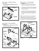
STEP 4: INSTALL LIFT BRACKET ASSEMBLY (SEE FIGURE 3) • Assemble the lift bracket assembly to the lift frame assembly using two 5/8" washers (II) and 1/8" x 1-1/4" cotter pins (BB). STEP 6: INSTALL LIFT STRAP ASSEMBLIES (SEE FIGURE 5) • Loosen the bolts and nuts on the lift strap assemblies 1/4 turn or until the straps will slide back and forth. You will retighten them later in step 26. • Turn the lift strap assemblies as shown.
STEP 8: INSTALL STOP BRACKET BOLT (SEE FIGURE 7A) For lift straps installed in front holes • Install the long compression spring (PP) and then the two 5/8" spacers (X) onto the 5/16" x 3-1/2" hex bolt (H). Insert the bolt into the stop bracket and install two 5/16" hex nuts (T) onto the bolt. Adjust nuts later in step 29.
STEP 11: INSTALL TILT STOP BRACKETS (SEE FIGURE 10) • Install a tilt stop bracket (RR) to each side of the bucket using a 3/8" x 1" carriage bolt (J), a small 3/8" washer (FF) and 3/8" nylock nut (R). Do not tighten the nuts until step 28. STEP 9: INSTALL DUMP PIVOT BRACKET (SEE FIGURE 8) • Install a 1/8" x 1-1/2" cotter pin (CC) to the inside hole in the shaft shown in figure 8, and then install a 1" washer (LL) onto the shaft.
STEP 15: INSTALL DUMP HANDLE TUBE (SEE FIGURE 14) DUMP • Install the dumpHANDLE handle tube to the dump pivot bracket assembly usingTUBE three 5/16" x 1-3/4" hex bolts (G) and 5/16" nylock nuts (S). STEP 13: INSTALL LIFT HANDLE TUBE EXTENSION (SEE FIGURE 12) • Install the lift handle tube extension on the lift handle tube using a 1/4" x 1-3/4" hex bolt (I) and 1/4" nylock nut (U).
STEP 18: INSTALL HOSE CLIP AND SPACER (SEE FIGURE 17) • Secure the dump cable to the back of the bucket using a hose clip (SS), a #10 x 5/8" truss-head bolt (L) and a #10-32 nylock nut (W). STEP 17: INSTALL DUMP CONTROL PIN (SEE FIGURE 16) • Install a small 1/2" washer (GG) and then the short compression spring (OO) onto the dump control pin. Install the dump control pin into the pin stop bracket. Make sure the flat side of the pin faces to the front when finished.
LAWN TRACTORS AND GARDEN TRACTORS WITH SINGLE SUSPENSION BRACKETS STEP 21: INSTALL FRAME BRACE (SEE FIGURE 20) • Install the frame brace to the inside of the side plates using two 1/2" x 1-3/4" bolts (B), large 1/2" washers (JJ), 1/2" spacers (Y) and 1/2" nylock nuts (O). Install the brace in the bottom holes for Garden (GT) Tractors and the second from bottom holes for Lawn (LT) Tractors. Do not tighten yet.
LAWN TRACTORS WITH DUAL SUSPENSION BRACKETS GARDEN TRACTORS WITH DUAL SUSPENSION BRACKETS STEP 22: INSTALL SIDE PLATES (SEE FIGURE 21) • Remove any bolts present in the mounting holes on the left side of the tractor frame. Do not remove bolts from right side of frame until done with left side plate. STEP 24: INSTALL SIDE PLATES (SEE FIGURE 23) • Remove any bolts present in the mounting holes on the left side of the tractor frame.
INSTRUCTIONS FOR all tractors STEP 26: ADJUST TILT AND PIN STOP BRACKETS (SEE FIGURE 25) • Lower the scoop assembly onto a smooth level surface. For normal use, let the bottom of the bucket rest flat on the ground. For more aggressive scraping action, place 1/4" shims under the rear of the bucket at each end. STEP 25: MOUNT SCOOP TO TRACTOR (SEE FIGURE 24) • Align the scoop with the side plates on the front of the tractor.
STEP 27: ADJUST LIFT STRAPS (SEE FIGURE 26) • Make sure the nuts and bolts in the lift straps are loose enough to turn by hand. Stand beside the right side of the scoop and hold the lift handle as far forward as it will go until you tighten one of the nuts in the lift straps. Let go of the lift handle and tighten the other three nuts in the lift straps. STEP 29: ADJUST STOP BOLT (SEE FIGURE 28) • Keep the scoop locked in the TRANSPORT position.
OPERATION KNOW YOUR Front end scoop • Always test to make sure your vehicle has adequate power and braking capabilities whenever hauling a substantial amount of weight in your front end scoop. Use extra caution when operating on slopes. Read this owner's manual and safety rules before operating your front end scoop. Compare the illustration below with your front end scoop to familiarize yourself with the various controls and their locations.
MAINTENANCE CUSTOMER RESPONSIBILITIES • Read and follow the maintenance schedule and the maintenance procedures listed in this section. MAINTENANCE SCHEDULE Fill in dates as you complete regular service.
TROUBLESHOOTING PROBLEM Scoop won't lock into raised/transport position. Scoop bucket won't lock into level position after dumping. CAUSE CORRECTION 1. Index rod is jamming. 2. Frame is hitting tilt stop brackets. 1. Apply grease to the bottom slot in the lift bracket, where the index rod slides 2. Adjust the tilt stop brackets as instructed on page 16. 1. Dump control pin does not align with the tilt bracket. 1. Adjust the tilt bracket and lift straps as instructed on page 16. 2.
PARTS REPAIR PARTS FOR MODEL 486.
REPAIR PARTS FOR MODEL 486.248475 ref part no. qty description ref part no. qty description 1 1509-69 3 Hex Bolt, 1/4-20 x 1-3/4" (Grade 5) 43 43093 3 Cotter Pin, 1/8" x 1-1/2" 2 726-0178 6 Cable Tie 44 710-0865 3 Hex Bolt, 1/2-13 x 1" (Grade 5) 3 49265 1 Lift Handle Extension 45 R19212016 6 Flat Washer, 5/8" x 1-1/4" x 16 Ga. 4 49266 2 Oval Screw, 10-24 x 1-1/2" 46 25852 1 Tilt Bracket Extension Strap 5 47674 2 Plastic Plug, 1-1/4" O.D. Tube 47 25851 1 Tilt Bracket 6 47025 1 Hex Bolt, 5/16-18 x 3-1/2" (Gr.
NOTES 22
SUGGESTED GUIDE FOR SIGHTING SLOPES FOR SAFE OPERATION OF TRACTOR WITH ATTACHMENT FOLD ALO N G D THIS IS OTTED LINE A 10 D E G REE S LOPE ONLY RIDE UP AND DOWN HILL, NOT ACROSS HILL 10 DEGREES MAX. WARNING: To avoid serious injury, operate your tractor up and down the face of slopes, never across the face. Do not operate on slopes greater than 10 degrees. Make turns gradually to prevent tipping or loss of control. Exercise extreme caution when changing direction on slopes.
Product questions or problems? 1-888-331-4569 Customer Care Hot Line Get answers to questions, troubleshoot problems, order parts, or schedule repair service. Para respuestas a preguntas o problemas, y ordenar piezas o pedir servicio para la reparación de su equipo. To help us help you, register your product at www.craftsman.com/registration Para poderte ayudar mejor, registra tu producto en www.craftsman.