
Owner's Manual


10
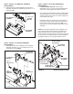
5/16" x 1-3/4"
HEX BO L T (G)
5/16" NYLOCK
NUTS (S)
LIFT HANDLE
TUBE
INDEX
BR A CKE T
FIGURE 11
STEP 12: INSTALL LIFT HANDLE TUBE
(SEE FIGURE 11)
• Installthelifthandletubeintotheindexbracketusing
two5/16"x1-3/4"hexbolts(G)and5/16"nylocknuts
(S).
TILT STOP
BRACKET (RR)
3/8" NYLOCK
NUT (R)
3/8" W ASHER (FF)
3/8" x 1"
CARRI A GE BO L T (J)
FIGURE 10
STEP 11: INSTALL TILT STOP BRACKETS
(SEE FIGURE 10)
• Installatiltstopbracket(RR)toeachsideofthe
bucketusinga3/8"x1"carriagebolt(J),asmall3/8"
washer (FF) and 3/8" nylock nut (R). Do not tighten
the nuts until step 28.
5/8" W ASHERS (II)
5/8" WASHERS (II)
1/8" x 1-1/4"
COTTER PIN (BB)
1/8" x 1-1/4"
C O TTER PI N (BB)
DUMP
CONT R O L
R O D
1/8" x 1-1/4"
C O TTE R
PINS (BB)
FIGURE 9
STEP 10: INSTALL DUMP CONTROL ROD
(SEE FIGURE 9)
• Installa1/8"x1-1/4"cotterpin(BB)intotheinsidehole
in each end of the dump control rod. Spread the ends
of the cotter pins and wrap around the rod. Install a 5/8"
washer (II) onto each end of the control rod.
• Installthedumpcontrolrodtothedumppivotbracket
andbucket.Fastenusingtwo5/8"washers(II)and
1/8" x 1-1/4" cotter pins (BB). Spread the ends of the
cotter pins and wrap around the rod.
1" W ASHERS (LL)
1/8" x 1-1/2"
C O TTER PI N (CC)
APP L Y
GREASE
DUMP PI V O T
BR A CKE T
1/8" x 1-1/2"
C O TTER PI N (CC)
FIGURE 8
STEP 9: INSTALL DUMP PIVOT BRACKET
(SEE FIGURE 8)
• Installa1/8"x1-1/2"cotterpin(CC)totheinsidehole
intheshaftshowningure8,andtheninstalla1"
washer (LL) onto the shaft. Apply grease to the end of
theshaftandinstallthedumppivotbracketassembly
onto the shaft. Install a 1" washer (LL) onto the shaft
and secure it using a 1/8" x 1-1/2" cotter pin (CC).