Operator’s Manual 10 IN. JOBSITE TABLE SAW Model No. 137.415020 CAUTION: Before using this Table Saw, read this manual and follow all its Safety Rules and Operating Instructions Customer Help Line For Technical Support 1-800-843-1682 ● ● ● ● ● Safety Instructions Installation Operation Maintenance Parts List Sears Parts & Repair Center 1-888-331-4569 Sears Brands Management Corporation Hoffman Estates, IL 60179 USA See the full line of Craftsman® products at craftsman.
TABLE OF CONTENTS SECTION Warranty ............................................................................................................. Product Specifications ........................................................................................ Symbols............................................................................................................... Power Tool Safety ............................................................................................... Table Saw Safety ....
product specifications MOTOR Type............................................................................. Amperes....................................................................... Voltage........................................................................ Hz................................................................................ RPM (no load) ............................................................ Overload Protection....................................................
Symbols WARNING ICONS Your power tool and its Operator’s Manual may contain “WARNING ICONS” (a picture symbol intended to alert you to, and/or instruct you how to avoid, a potentially hazardous condition). Understanding and heeding these symbols will help you operate your tool better and safer. Shown below are some of the symbols you may see. SAFETY ALERT: Precautions that involve your safety. PROHIBITION WEAR EYE PROTECTION: Always wear safety goggles or safety glasses with side shields.
power tool safety GENERAL SAFETY INSTRUCTIONS BEFORE USING THIS POWER TOOL 5. DO NOT USE IN DANGEROUS ENVIRONMENTS. Do not use power tools in damp locations, or expose them to rain or snow. Keep work area well lit. 6. KEEP CHILDREN AWAY. All visitors and bystanders should be kept a safe distance from work area. Safety is a combination of common sense, staying alert and knowing how to use your power tool.
16.REDUCE THE RISK OF UNINTENTIONAL STARTING. Make sure switch is in the OFF position before plugging the tool in. 11.WEAR PROPER APPAREL. Do not wear loose clothing, gloves, neckties, rings, bracelets or other jewelry which may get caught in moving parts. Nonslip footwear is recommended. Wear protective hair covering to contain long hair. 12. 13. 14. 17.USE RECOMMENDED ACCESSORIES. Consult this Operator’s Manual for recommended accessories.
21.DO NOT OVERREACH. Keep proper footing and balance at all times. 25. ! WARNING 26. ! Dust generated from certain materials can be hazardous to your health. Always operate saw in wellventilated area and provide for proper dust removal. 22. MAINTAIN TOOLS WITH CARE. Keep tools sharp and clean for best and safest performance. Follow instructions for lubricating and changing accessories. 23. DO NOT use power tool in presence of flammable liquids or gases. 24.
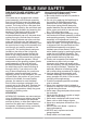
TABLE SAW SAFETY 1. ALWAYS USE SAW BLADE GUARD, riving knife and antikickback pawls for every through– sawing operation. Through–sawing operations are those in which the blade cuts completely through the workpiece when ripping or crosscutting. Always be sure blade guard is tightened securely. 6. NEVER REACH behind or over the cutting tool for any reason. 7. REMOVE the rip fence when crosscutting. 8. DO NOT USE a molding head with this saw. 9. DIRECTION OF FEED.
14.AVOID AWKWARD OPERATIONS and hand positions where a sudden slip could cause your hand to move into the saw blade. 20.For proper operation follow the instructions in this Instruction Manual entitled ASSEMBLY AND ADJUSTMENTS (Page 19). Failure to provide sawdust fall-through and removal hole will allow sawdust to build up in the motor area resulting in a fire hazard and potential motor damage. 15.NEVER USE SOLVENTS to clean plastic parts. Solvents could possibly dissolve or otherwise damage the material.
TABLE SAW safety How to Avoid Kickbacks and Protect Yourself from Possible Injury: a. Be certain that the rip fence is parallel to the saw blade. b. Do not rip by applying the feed force to the section of the workpiece that will become the cut-off (free) piece. Feed force when ripping should always be applied between the saw blade and the fence; use a push stick for narrow work, 6 in. (152 mm) wide or less. c.
electrical requirements and safety equipment grounding conductor. If repair or replacement of the electrical cord or plug is necessary, do not connect the equipment grounding conductor to a live terminal. POWER SUPPLY AND MOTOR SPECIFICATIONS ! WARNING To avoid electrical hazards, fire hazards, or damage to the tool, use proper circuit protection. Use a seperate electrical circuit for your tool. Your table saw is wired at the factory for 120V operation.
GUIDELINES FOR EXTENSION CORDS Fig. 1 Three-Pronged Plug Make sure your extension cord is properly wired and in good condition. Always replace a damaged extension cord or have it repaired by a qualified technician before using it. Protect your extension cords from sharp objects, excessive heat and damp or wet areas.
tools needed for assembly ACCESSORIES AND ATTACHMENTS RECOMMENDED ACCESSORIES SUPPLIED NOT SUPPLIED Blade wrench Flat bladed screwdriver 4 mm hex wrench Phillips screwdriver ! WARNING Visit your Sears Hardware Department or see the Craftsman Power and Hand Tools Catalog to purchase recommended accessories for this power tool. 10K1 DADO INSERT PLATE ! WARNING 5 mm hex wrench To avoid the risk of personal injury: ● Do not use adjustable (wobble) type dadoes or carbide tipped dado blades.
carton contents Separate all parts from packing materials. Check each part with the illustration on the next page and the “Table of Loose Parts” to make certain all items are accounted for, before discarding any packing material. NOTE: To make assembly easier, keep contents of box together. ! WARNING If any part is missing or damaged, do not attempt to assemble the table saw, plug in the power cord, or turn the switch ON until the missing or damaged part is obtained and is installed correctly.
UNPACKING YOUR TABLE SAW B A C E D F H G I K J M L N 15
know your table saw Table insert Miter gauge Rip fence Push stick storage extension table locking lever Rip fence storage Blade elevation and tilting handwheel Miter gauge storage Overload reset switch ON/OFF switch with safety key Stand handles Wheel Adjustable foot pad Blade guard Blade Riving knife Anti-kickback pawls Right extension table Power cord storage Blade/Blade wrench storage stand lock lever Dust port Blade guard and Anti-kickback pawls storage Stand 16
GLOSSARY OF TERMS FREEHAND – Performing a cut without using a rip fence, miter gauge, hold down or other proper device to prevent the workpiece from twisting during the cutting operation. ANTI-KICKBACK PAWLS – To prevent the workpiece being kicked upward or back toward the front of the table saw by the spinning blade. ARBOR – The shaft on which the blade or dado is mounted. GUM – A sticky sap from wood products. BEVEL CUT – An angle cut made through the face of the workpiece.
OVERLOAD RESET SWITCH – Protects the motor if it overloads during operation, provides a way to restart the saw. SAW BLADE PATH – The area of the workpiece or table top directly in line with the travel of the blade or the part of the workpiece that will be cut. PUSH STICK – Used to push workpieces when performing ripping operations. SET – The distance between two saw blade tips, bent outward in opposite directions to each other. The further apart the tips are, the greater the set.
ASSEMBLY AND ADJUSTMENTS ! WARNING Fig. B Right Side For your safety, never connect plug to power source receptacle until all assembly and adjustment steps are complete, and you have read and understood the safety instructions. C A B ASSEMBLING THE WHEELS TO STAND (FIG. A) 1. Attach one wheel (1) to the leg using the long hex bolt (2), the two flat washers (3) and the lock nut (4), as shown in Fig. A. Tighten the lock nut (4) using a 14 mm wrench. 2.
MOUNTING TABLE SAW TO STAND (FIG. E) 1. Lift the saw body (1) and place on the stand (2), aligning the four mounting holes (3) of the saw base with the four mounting holes (4) on the top plate of stand. 2. Attach the table saw to the stand with four hex head bolts (5) and washers (6). 3. Tighten all mounting bolts with a 13 mm wrench. ! 2. Rotate the hook (1) to the stop screw to secure the legs of the stand in position. (Fig. B) 3. Rest the right side of the saw onto the floor. 4.
Blade and blade wrench (Fig. I) The storage for the blade (1) and blade wrench is Iocated on the right side of the saw housing. STORAGE (FIG. G, H, I, J, K, L, M, N) Rip fence and miter gauge (Fig. G) The storage for the rip fence (1) and miter gauge (2) are built into the base and are located on the left side of the saw housing. 1. Loosen and remove the knob (2), place the blade (1) and blade wrench (3) on to the arbor. Replace the knob (2) and tighten. Fig. G Fig. I 3 1 2 2 1 Push stick (Fig.
Blade guard (Fig. K) The storage for the blade guard is located on the right side of the stand. 1. Take the blade guard (1) and press down on the red spring button (2) located on the top. 2. Position the blade guard (1) and align the slot (3) over the set plate (4). 3. Lower the blade guard (1) onto the set plate (4), and release the red spring button (2) so that two latches (5) engage into two locking hooks (6) completely. Fig. L 5 3 4 1 2 Riving knife (Fig.
Fig. N INSTALLING THE BLADE (FIG. P, Q, R) 1 3 2 ! WARNING To avoid injury from an accidental start, make sure the switch is in the OFF position and the plug is not connected to the power source outlet. 1. Remove the table insert (1) by inserting your finger into the opening (2) and pulling up. Raise the blade to the maximum height by turning the blade elevation handwheel clockwise. (Fig. P) 1 Installing the handwheel HANDLE (FIG. O) NOTE: UP-DOWN is printed on this handwheel. 1.
REMOVING THE BLADE (FIG. P, Q, R) 3. Place the blade onto the arbor (5) with the blade teeth pointing forward to the front of the saw. (Fig. Q) NOTE: Leave the plastic strip around the saw blade at this time. Remove before using the saw for the first time. 4. Make sure the blade fits flush against the inner flange (6). 5. Clean the outer blade flange (4) and install it onto the arbor (5) and against the blade. (Fig. Q) 6.
RIVING KNIFE ASSEMBLY ! ! WARNING ● To avoid injury from an accidental start, make sure the switch is in the OFF position and the plug is disconnected from the power source outlet. ● Never operate this saw without the riving knife in the correct position. ● DO NOT operate saw if riving knife is not locked in the throughcut slot (A) or non through-cut position slot (B).
Fig. U 5. Tilt the blade to the 45° position and check the alignment again. NOTE: ● This table saw is provided with a 10 inch diameter blade with a body thickness of 0.07 in. (1.8 mm) thick with a kerf of 0.10 in. (2.6 mm ).The riving knife is 0.09 in. (2.2 mm) thick.The blade diameter and the blade body and kerf dimensions must be properly matched with the riving knife thickness. ● The maximum radial distance between the riving knife and the toothed rim of the saw blade is 0.12 in ~ 0.31 in.
BLADE GUARD AND ANTIKICKBACK PAWL ASSEMBLY ADDITIONAL BLADE ADJUSTMENTS (FIG. W) 1. If the front and rear measurements are not the same, remove the combination square and loosen the four adjusting screws (1) on the top of the table about a half turn. 2. Cover the blade with a folded piece of cardboard to protect your hands. Move the blade and motor mounting rod carefully to the left or right as much as needed to align the blade correctly. 3.
Fig. Y removing the anti-kickback pawls and blade guard assembly (Fig. AA, BB) 3 Tighten ! WARNING To avoid injury from an accidental start, make sure the switch is in the OFF position and the plug is disconnected from the power source outlet. 1. With the blade elevation handwheel raise the blade to the maximum height. 2. Loosen the bevel lock knob and then turn the handwheel to 0° on the bevel scale. 3. Tighten the bevel lock knob. 4.
3. Lock the fence handle. The fence should be parallel with the miter gauge groove. 4. If adjustment is needed to make the fence parallel to the groove, do the following: ● Loosen the two bolts (3) and lift up on the handle (2). ● Hold the fence bracket (4) firmly against the front of the saw table. Move the fence until it is parallel with the miter gauge groove. ● Push the handle down and tighten both bolts. 5.
3. To change angles on the miter gauge, loosen the lock handle (1) and rotate the miter body to the desired angle as indicated by the scale. Secure in position by tightening the lock handle. RIP FENCE INDICATOR ADJUSTMENT (FIG. DD) 1. The rip fence indicator (1) points to the measurement scale. The scale shows the distance from the side of the fence to nearest side of the blade. 2. Measure the actual distance with a rule.
90° AND 45° POSITIVE STOPS ADJUSTMENT (FIG. GG, HH) Your saw has positive stops that will quickly position the saw blade at 90° and 45° to the table. Make adjustments only if necessary. 45° Stop 1. Disconnect the saw from the power source. 2. Raise the blade to the maximum elevation. 3. Loosen the bevel lock knob and move the blade to the maximum bevel position (45°) and tighten the bevel lock knob. 4.
BLADE TILTING SCALE INDICATOR (FIG. II) 1. When the blade is positioned at 90°, adjust the blade tilting scale indicator to read 0 ° on the scale. 2. Loosen the holding screw (1), position the pointer over 0° and tighten the screw (1). NOTE: Make a trial cut on scrap wood before making critical cuts. Measure for accuracy. 1. Remove the safety switch key and unplug the saw. 2. Remove the blade guard for this procedure but reinstall and realign after adjustment. 3.
LOCKING LEVER ADJUSTMENT (FIG. KK) If the extension table moves when it is open and locked in place, the cam locking lever (1) may be loose and require adjustment. To adjust the locking lever tension, turn the bar (2) with a 10 mm wrench until it is tightened correctly. Do not over tighten! Fig.
Operation BASIC SAW OPERATIONS 1. To turn the saw ON, insert the safety key (1) into the slot in the switch (2). Move the switch upward to the ON position. 2. To turn the saw OFF, move the switch downward. 3. To lock the switch in the OFF position, grasp the end (or yellow part) of the safety key (1), and pull it out. 4. With the safety key removed, the switch will not operate. 5.
when the reset button is pushed. Overheating may be caused by misaligned parts or a dull blade or undersized extensing cord. Inspect your saw for proper setup before using it again. Fig. OO USING THE DUST PORT (FIG. NN) 2 ! WARNING To prevent fire hazard, clean and remove sawdust from under the saw frequently. CUTTING OPERATIONS There are two basic types of cuts: ripping and crosscutting. Ripping is cutting along the length and the grain of the workpiece.
RIPPING (FIG. PP, QQ) ! ! WARNING To prevent serious injury: ● Never use a miter gauge when ripping. ● Never use more than one rip fence during a single cut. ● Do not allow familiarity or frequent use of your table saw to cause careless mistakes. Remember that even a careless fraction of a second is enough to cause a severe injury. ● Keep both hands away from the blade and clear from the path of the blade.
featherboard (Fig. RR, SS) A featherboard is a device used to help control the workpiece by guiding it securely against the table or fence. Featherboards are especially useful when ripping small workpieces and for completing non-through cuts. The end is angled with a number of short kerfs to give a friction hold on the workpiece and locked in place on the table with C-clamps. Test that it can resist kickback. 9. Never pull the workpiece back when the blade is turning. Turn the switch OFF.
5. Attached the C-clamps (5) to secure the featherboard to the edge of the table. Fig. SS 1 3 2 21 in 3/8 in 4 3/8 in. thick plywood base 5 3/8 The edge must be parallel with the face AUXILIARY FENCE (FIG. TT) Making the base: ● Start with a piece of 3/8 in. plywood at least 5-1/2 in. wide or wider and 21 in. long or longer. ● Cut the piece to shape and size as shown. Making the side: ● Start with a piece of 3/4 in. hardwood at least 1-3/4 in. wide or wider and 21 in. long or longer.
! 1. Remove the rip fence and place the miter gauge in the miter gauge groove on the table. 2. Adjust the blade height so that it is 1/8 in. higher than the top of the workpiece. 3. Hold the workpiece firmly against the miter gauge with the blade path in line with the desired cut location. Move the workpiece to a 1 in. distance from the blade. 4. Start the saw and wait for the blade (1) to come up to full speed.
USING THE WOOD FACING ON THE MITER GAUGE (FIG. WW) Slots are provided in the miter gauge for attaching an auxiliary facing (1) to make it easier to cut very long or short pieces. Select a suitable piece of smooth wood, drill two holes through it and attach it to the miter gauge with screws. Make sure the facing does not interfere with the proper operation of the saw blade guard. When cutting long workpieces, you can make a simple outfeed support by clamping a piece of plywood to a sawhorse. 3.
COMPOUND CROSSCUTTING (FIG. ZZ) 0°~45° Blade bevel & 0°~45° Miter angle This sawing operation combines a miter angle with a bevel angle. 2. Attach the wood facing to the fence with wood screws (3) (not included) through the holes in the fence. A wood fence should be used when ripping material such as thin paneling to prevent the material from catching between the bottom of the fence and the table. ! WARNING Always work to the right side of the blade during this type of cut.
DADO CUTS (Fig. cc, dd) 1. Before starting the table saw, lower the blade and riving knife assembly to the down position. 2. Remove the blade guard assembly and anti-kickback pawls assembly for non-through cut. 3. Use the featherboard (1) with C-clamps (3) to fasten the workpiece securely. 4. Mount the auxiliary fence (4) with C-clamps. 5. Use the push block (2) to move the workpiece. NOTE: Mount the featherboard to table as shown, so the leading edges of featherboard will help workpiece complete cutting.
Fig. cc 2 1 3 7. Check the saw to ensure that the dado will not strike the housing, insert, or motor when in operation. ! WARNING For your own safety, always replace the blade, blade guard assembly, anti-kickback pawls, riving knife and table insert when you finished the dado operation. Fig.
maintenance MAINTAINING YOUR TABLE SAW BLADE RAISING AND TILTING MECHANISM (FIG. ee) After every five hours of operation, the blade raising mechanism and tilting mechanism should be checked for looseness, binding, or any other abnormalities. 1. With the saw disconnected from the power source, turn the saw upside down and pull up and push down on the motor unit. 2. Observe any movement of the motor mounting mechanism. Loosen or play in the blade raising screw rod (1) should be limited to 1/8 in. or less. 3.
9. Place the new brush into the opening of motor, making sure the ears on the metal end of the assembly go in the same hole the carbon part fits into. Do not overtighten the plastic cap. 10. Carefully set the saw in a upright position on a clean level surface. 11. Replace the blade guard, blade, rip fence, miter gauge and stand assembly to the table saw. NOTE: To reinstall the same brushes, first make sure the brushes go back in the same sides they came out.
troubleshooting guide ! WARNING To avoid injury from accidental starting, always turn switch OFF and unplug the tool before moving, replacing the blade or making adjustments. PROBLEM POSSIBLE CAUSES CORRECTIVE ACTION Saw will not start. 1. Saw is not plugged in. 2. Fuse blown or circuit breaker tripped. 3. Cord is damaged. 4. Debris in on/off switch 1. Plug in saw. 2. Replace fuse or reset circuit breaker. 3. Replace power cord. 4. Remove switch from saw and separate in half.
! WARNING To avoid injury from accidental starting, always turn switch OFF and unplug the tool before moving, replacing the blade or making adjustments. PROBLEM POSSIBLE CAUSES Material kicked 1. Rip fence out of adjustment. back from blade. 2. Riving knife not aligned with blade. 3. Feeding stock without rip fence. 4. Riving knife not in place. 5. Dull blade. 6. The operator letting go of material before it is past saw blade. 7. Miter angle lock knob is not tight.
Push stick construction ● Use good quality plywood or solid wood ● Use 1/2 in. or 3/4 in. material ● Push stick MUST be thinner than the width of material being cut 0m m) Drill Hole For Hanging 15 -3/ 4i n. (40 Notch To Prevent Hand From Slipping Cut Here To Push 1/2 in. Wood Cut Here To Push 3/4 in.
10 IN. table SAW ! MODEL NO. 137.415020 WARNING When servicing use only CRAFTSMAN replacement parts. Use of any other parts many create a HAZARD or cause product damage. Any attempt to repair or replace electrical parts on this Table Saw may create a HAZARD unless repair is done by a qualified service technician. Repair service is available at your nearest Sears Service Center. PARTS LIST FOR TABLE SAW - A I.D. NO. Description Size Q’ty I.D. NO.
10 IN. table SAW MODEL NO. 137.415020 PARTS LIST FOR TABLE SAW SCHEMATIC - B I.D. NO. Description Size Q’ty I.D. NO.
10 IN. table SAW MODEL NO. 137.
10 IN. table SAW MODEL NO. 137.415020 PARTS LIST FOR MOTOR ID NO. Description 0HV4 BALL BEARING Size Q’ty 1 0HX9 NEEDLE BEARING 1 0JB8 WAVE WASHER 1 0JBA WAVE WASHER 1 0JE0 C-RING 1 0JEE C-RING 1 0JGA PARALLEL KEY 0JX3 HEX. SOC. SET SCREW M5*0.8-8 2 0K3F CR.RE. PAN HD. SCREW & WASHER M5*0.8-20 1 0K44 CR.RE. PAN HD. SCREW & WASHER M5*0.
10 IN. table SAW MODEL NO. 137.415020 PARTS LIST FOR STAND ID NO. 3671 0J4F 0J4R 0J4W 0JB0 0JPR 0JUL 0JVB 0K75 0KMV 0KQW 0KQX 0KQY 157B 271T 2JF1 2MA8 2T9J 2WV3 2WV7 2WVF 2X2G 2XGE 2Y7K 31YC 34XF 35ME Description FOAM HANDLE FLAT WASHER FLAT WASHER FLAT WASHER WAVE WASHER HEX. HD. BOLT HEX. SOC. HD. CAP BOLT HEX. SOC. HD. CAP BOLT CR.-RE. TRUSS HD. SCREW HEX. NUT LOCK NUT NUT LOCK NUT HEX. SOC. HD. CAP BOLT FLAT WASHER HEX. SOC. TRUSS HD. SCREW WING NUT CR.RE. PAN HD.
Repair protection Agreements Congratulations on making a smart purchase. Your new Craftsman® product is designed and manufactured for years of dependable operation. But like all products, it may require repair from time to time. That’s when having a Repair Protection Agreement can save you money and aggravation.
NOTES 55
NOTES 56