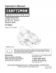
perator s P R 0 F E S S I 0 N A LAWN TRACTOR 24 HP, 42" Tractor Electric Start PYT9000 Model No. 247.28672 • EspaSol, p. 62 This product has a low emission engine which operates differently from previously built engines. Before you start the engine, read and understand this Operator's Manual. iMPORTANT: For answers to your questions this product, Call: Read and follow all Safety Rules and instructions before operating about 1=800=659=5917 this equipment.
Warranty Statement .......................................................... Safety instructions ............................................................ Safety Labels .................................................................... Assembly ......................................................................... Know your Lawn Mower .................................................. Operation ........................................................................
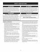
This machinewas builtto be operatedaccordingto the safeoperation practicesin this manual.As with anytype of powerequipment, carelessnessor error on the partof the operatorcan resultin serious injury.This machineis capableof amputatingfingers,hands,toes and feet and throwingdebris.Failureto observethe followingsafety instructionscouldresultin seriousinjuryor death. This symbolpointsout importantsafetyinstructionswhich,if not followed,couldendangerthepersonalsafetyand/orpropertyof yourselfand others.
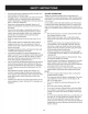
• SLOPE Slowdownbeforeturning.Operatethe machinesmoothly.Avoid erraticoperationand excessivespeed. Disengageblade(s),set parkingbrake,stopengine and wait until the blade(s)come to a completestop beforeremovinggrass catcher,emptyinggrass,uncloggingchute,removinganygrass or debris,or makinganyadjustments. OPERATION Slopesare a majorfactorrelatedto loss of controland tip-over accidentswhichcan result in severeinjuryor death.All slopes require extra caution.
CHILDREN SERVICE Tragicaccidentscanoccur ifthe operatoris notalert to the presence of children.Childrenare often attractedto the machineand the mowing activity.They do notunderstandthe dangers.Neverassumethat childrenwill remainwhereyou last sawthem. • Keepchildrenout of the mowingareaand inwatchfulcare of a responsibleadultotherthanthe operator. • Be alert and turnmachineoff ifa childentersthe area. SafeHandlingof Gasoline Toavoidpersonalinjuryor propertydamageuse extremecarein handlinggasoline.
General Service • Donot changethe enginegovernorsettingsor over-speedthe engine.The governorcontrolsthe maximumsafe operatingspeed • Never runanengine indoors orina poorly ventilated area.Engine of the engine. exhaust contains carbon monoxide, anodorless, anddeadly gas. Maintainor replacesafetyand instructionlabels,as necessary. • Before cleaning, repairing, orinspecting, make certain the blade(s) andallmoving partshave stopped.
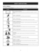
SAFETY SYMBOLS This pagedepictsand describessafety symbolsthat may appearon this product. Read,understand,and follow all instructions on the machine beforeattemptingto assembleand operate. READ THE OPERATOR'S MANUAL(S) Read, understand, and follow all instructions in the manual(s) before attempting to assemble and operate DANGER-- ROTATING BLADES Never carry passengers. Never carry children, even with the blades off.
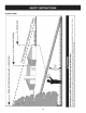
SLOPE GUIDE (.... "'O Or) C;) (=) (== CL) C3, %,==,= (1) c_3 (1) }==== C) _== & 1>-. 03 E c_3 %,==,== C) x o _r }=== (1) _== cL 03 (1) cL o co "_--- (D 03 O Dm m_ I }==,== C) (=3 I v_ i c_3 _2 I I }==== C) I --_ o I ! I l }=.== l m (=) l cz l _r o l }==== l G.) 1> 0_3 0 l c 03 "o l E I I _== Q o _E (3) OO 8 _== I I C:) _= 03 03 _.
WARNING This symbol points out important safety instructions which, if not followed, could endanger the personal safety and/or property of yourself and others. Read and follow all instructions in this manual before attempting to operate this machine. Failureto comply with these instructions may result in personal injury.
TRACTOR SET-UP Moving The Tractor Shipping Removal Manually Yourtractor'stransmissionis equippedwith a hydrostaticreliefvalve for occasionswhenit is necessaryto movethe tractormanually.Opening this valve permitsthe fluidin the transmissionto bypassits normal route,allowingthe rear tiresto "freewheel."Toopen the hydrostatic reliefvalve,proceedas follows: 1. Brace Makesurethe lawntractor'sengine isoff, set the parkingbrakeand removethe ignitionkey beforeremovingthe shippingbrace. 1.
CONNECTING THE BATTERY CABLES Setting Whenattachingbatterycables,alwaysconnectthe POSiTiVE(Red) wire to its terminalfirst, followedbythe NEGATIVE(Black) wire. 1. Selectthe heightpositionof the cuttingdeck by placingthe deck lift leverin the normallydesiredmowingheightsetting(anyof the six differentcuttingheightnotcheson the rightfender). 2. Checkthe gaugewheelsfor contactor excessiveclearancewith the surfacebelow.The deck gaugewheelsshouldhavebetween 1A"and Y2"clearanceabovethe ground.
Adjusting the Seat Toadjustthe positionof the seat,pull up and hold the seatadjustment lever.Slidethe seat forwardor rearwardto the desiredposition;then releasethe adjustmentlever.Makesureseat islockedintopositionin a seat-stopbeforeoperatingthe tractor.See Figure5. Beforeoperatingthe tractor,make surethe seatisengagedin a seat-stop.Engagethe parkingbrake.Standbehindthe machineand pull backon seat untilitclicks intoplace.
f IgnitionSwitch Module FueITankCap Throttle/ChokeControl_ I PTO(Blade Knob FuelLevelIndicator DrivePedal Pedal LiffLever Cup Holder" \ Figure6 BRAKE LawnTractorcontrolsand featuresare illustratedin Figure6 and describedon thefollowingpages. The brakepedalis locatedon the left front sideof the tractoralong the runningboard. The brakepedalcan be usedfor sudden stopsor settingthe parkingbrake.
iGNiTiON SWITCH MODULE Tostart theengine,insertthe key into the ignitionswitchand turnclockwise to the STARTposition.Releasethe key intothe NORMAL MOWING MODE positiononcethe enginehas fired. SYSTEMS INDICATOR METER LCD Whenthe ignitionkey is rotatedout of the STOP 0 positionbut not intothe START position,thesystem'sindicator monitordisplaysthe battery's output,in volts,on its LCDfor approximatelyfive seconds, after which it displaysan hour glass and the hoursof tractor operation.
FUEL LEVEL INDICATOR The FuelLevelIndicatorislocatedon the left sideof the tractor's dashand indicatesthe amountof fuelin the gastank. PTO/BLADE ENGAGE KNOB PTO Activatingthe PTOengagespowerto the cuttingdeck or other(separatelyavailable) attachments.Pull outwardon the PTO/Blade Engageknobto activateit. Pushthe PTO/ Blade Engageknobinwardto disengagethe powerto the cuttingdeck or other (separately available)attachments.
SAFETY iNTERLOCK SWITCH ES STOPPING This tractoris equippedwith a safetyinterlock systemfor the protection of the operator.If the interlocksystemshouldevermalfunction,do not operatethe tractor.Contacta Searsor otherqualifiedservicedealer. • • If you strikea foreignobject,stopthe engineand disconnectthe spark plugwire(s). Thoroughlyinspectthe machinefor anydamage. Repairthedamagebeforerestartingand operating.
REVERSE CAUTION MODE DRIVING The REVERSECAUTIONMODEpositionof thekey switch module allowsthe tractorto be operatedin reversewith the blades(PTO) engaged. Referto the SLOPEGUIDEon page8 to help determineslopeswhere you mayoperatethe tractorsafely. NOTE: Mowingin reverseis not recommended. Donot mowon inclineswith a slopein excessof 15degrees(a rise approximately2-1/2feet every 10feet).The tractorcouldoverturnanc cause seriousinjury.
Cruise Control 2. Pullthe PTO/BladeEngageknob backinto theengaged(ON) position.See Figure9. NOTE: Alwaysoperatethe tractorwith the Throttle/Chokecontrollever in the FAST(rabbit)positionfor the mostefficientuseof the cutting deck or other(separatelyavailable)attachments. Neverengagethe cruise controlleverwhiletravelingin reverse. Toset the cruisecontrol: f 1. Slowlypressthe upper portionof thedrive pedalwith your right foot untilthe desiredspeedisachieved. 2.
Beforeperforminganytypeof maintenance/service, disengageall controlsandstoptheengine.Waituntilall movingpartshavecometo a completestop.Disconnectsparkplugwireandgroundit againstthe engineto preventunintendedstarting.Alwayswearsafetyglassesduring operationor whileperforminganyadjustments or repairs. BeforeEachUse Followthe maintenanceschedulegivenbelow.This chart describes serviceguidelinesonly. Usethe Service Logcolumnto keeptrackof completedmaintenancetasks.
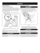
CUTTING DECK REMOVAL Placethe PTO/BladeEngageknobin the disengaged(OFF) positionand engagethe parkingbrake. . . Lowerthe deck by movingthe deck lift leverintothe bottomnotch on the rightfender. NOTE: If there is too muchtensionon thebelt for it to be easily removedfromthe electricPTOclutch,carefullyinsert a 3/8" drive ratchetwrench(set to loosen)intothe squareholefound in the deck idler bracketand pivotit towardthe tractor'sleft side to relievetension on the belt. See Figure11.
CHANGING . THE DECK BELT 8. TheV-belts foundon yourtractorare speciallydesignedto engage and disengagesafely.A substitute(non-OEM)V-beltcan be dangerous by notdisengagingcompletely.Fora properworkingmachine, use factoryapprovedbeltsas listedin the PartsList manualincluded with this product.. . f All belts on yourtractorare subjectto wearand shouldbe replacedif any signsof wear are present.Tochangeor replacethe deck belt on yourtractor,proceedas follows: 1. Removethe deck as instructedon page20. 2.
. CUTTING Toplacethe newbelt, begin by routingthe belt aroundthe two outerspindlepulleysas shownin Figure15. BLADES Shutthe engineoff and removeignitionkey beforeremovingthe cuttingblade(s)for sharpeningor replacement.Protectyourhands usingheavy gloveswhengraspingthe blade. Periodicallyinspectthe blade and/orspindlefor cracksor damage, especiallyafter you'vestrucka foreignobject.Do notoperatethe machineuntil damagedcomponentsare replaced. To removethe blades,proceedas follows: 1.
4. Toproperlysharpenthe cuttingblades,removeequal amounts of metalfrom both endsof the bladesalong the cuttingedges, parallelto thetrailingedge,at a 250.300angle.Alwaysgrindeach cuttingbladeedge equallyto maintainproperblade balance.See Figure18. If the cuttingedge of the bladehas previouslybeen sharpened,or if any metal separationis present,replacethe bladeswith newones. A poorlybalancedblade willcause excessivevibration,may cause damageto the tractorand/or result in personalinjury.
FUSE Althoughmulti-viscosityoils (5W20, 10W30,etc.) improvestarting in cold weather,theywill resultin increasedoil consumptionwhen usedabove32°RCheckyourengineoil levelmorefrequentlyto avoid possibleenginedamagefrom runninglowon oil. Beforeservicing,repairing,or inspecting, alwaysdisengagePTO (BladeEngageknob), set parkingbrake,stop engineand remove to preventunintendedstarting.
Changing the Engine Oil . 2. Removethe air filter cover. To removethe air filter,lift theend of the filter.See Figure21. f If the enginehas been recentlyrun,the engine,mufflerand surroundingmetal surfaceswill be hotand can causeburnsto the skin. Exercisecautionto avoidburns. /Cover NOTE:The oil filter shouldbe changedat every oil changeinterval.To completean oil change,proceedasfollows: 1. With engineOFF butstill warm,disconnectspark plugwire and keepit awayfrom spark plug. 2.
Fuel Filter IVluffler Gasolineand itsvaporsare extremelyflammableand explosive.Fire or explosioncan causesevereburnsor death. • Keepgasolineawayfrom sparks,open flames,pilotlights,heat, and otherignitionsources. • Checkfuel lines, tank,cap, and fittingsfrequentlyforcracks or leaks.Replaceif necessary.See a Searsor otherqualified servicedealerto replacefuel line. • Beforereplacingthe fuelfilter,drain the fueltank or closethe fuel shut-offvalve.
CLEANING THE TRACTOR 11. Turnthewater off and detach thehose couplerfrom the water porton your deck'ssurface. Anyfuel or oil spilledon the machineshouldbe wipedoff promptly.Do NOTallowdebristo accumulatearoundthecoolingfins of the engine, the transmission'scoolingfanor on any otherpartof themachine, especiallythebelts and pulleys. After cleaningyourdeck, returnto the operator'spositionand engage the PTO.
Deck Determinetheapproximatedistancenecessaryfor properadjustment and proceed,if necessary. Spindle Greasefittingscan be foundon eachdeck spindle.See Figure26. Lubricatewith 251HEP greaseor an equivalentNo. 2 multi-purpose lithiumgrease.Usinga greasegun, applytwo strokes(minimum)or sufficientgreaseto the spindleshaft. 1. To raisethe front of the deck,tighten(threadinward)the lock nut againstthe front hangerbracket.See Figure27. 2.
3. Loosen,butdo NOT remove,the hexbolt on the left deck hanger bracket.See Figure28. Steering Adjustment If the tractorturnstighter in one directionthanthe other,or if the ball joints are being replaceddue to damageor wear,the steeringdrag linksmay needto be adjusted. f Adjust thedrag links so that equal lengthsof each are threadedinto the ball joint on the left sideand the balljoint on the rightside: 1. Removethe hexnut belowthe balljoint. See Figure29. Hex Bolt ustment -Gear Figure28 4.
Neverstorelawntractorwith fuelin tank indoorsor in poorly ventilatedareaswherefuel fumesmay reachan openflame,spark, or pilot lightas on a furnace,water heater,clothesdryer,or gas appliance, PREPARING THE ENGINE PREPARING THE LAWN TRACTOR IMPORTANT:Fuelleft in the fueltank duringwarm weatherdeterioratesand will cause seriousstartingproblems. • Cleanand lubricatetractorthoroughlyas describedin the lubricationinstructions.
Beforeperforminganytypeof maintenance/service, disengageall controlsandstoptheengine.Waituntilall movingpartshavecometo a completestop.Disconnectsparkplugwireandgroundit againstthe engineto preventunintendedstarting.Alwayswearsafetyglassesduring operationor whileperforminganyadjustmentsor repairs. Thissectionaddresses minorservice issues.To locate the nearestSears Service Centeror to scheduleservice,simplycontactSears at 1-800-4-MY-HOME®. Enginefails to start 1. PTO/BladeEngageknobengaged. 1.
Mowerwill not mulchgrass Unevencut 1. Enginespeedtoo low. 1. PlaceThrottle/Chokecontrolin FAST(rabbit) position. 2. Wetgrass. 2. Do notmulchwhengrass is wet. 3. Excessivelyhigh grass. 3. Mowonce at a highcuttingheight,then mowagain at desiredheightor makea narrowercuttingswath. 4. Dullblade. 4. Sharpenor replaceblade. 1. Decknot leveledproperly. 1. Performside-to-sidedeck adjustment. 2. Dullblade. 2. Sharpenor replaceblade. 3. Uneventire pressure. 3.
Congratulationson makinga smartpurchase.YournewCraftsman@ productis designedand manufacturedfor yearsof dependableoperation. But likeall products,it may requirerepairfrom time to time.That's whenhavinga RepairProtectionAgreementcansave youmoneyand aggravation.
Steering and Axle -- IViodel No. 247.
Steering and Axle B IViodel No. 247.28672 710-04095 Hex HeadScrew,3/8-16:1.00 2 710-0514 Hex HeadScrew,3/8-16:1.00 22 638-04027-0637 LHAxle Assembly 710-0395 Hex HeadScrew,5/16-18:2.25 3 710-0643 Hex HeadScrew,5/16-18:1.00 23 710-0859 Hex HeadScrew,3/8-16:2.50 4 711-04998 iLH DragLink i24 710-3180 Hex HeadScrew,5/16-18:1.
Hood and Dash B IViodel No. 247.
Hood and Dash B IViodel No. 247.28672 631-04353P Dash Lever 731-07467 LowerGrill 2 710-04484 TaptiteScrew,LockWasher,5/16-18:.750 30 731-07469 LHHoodScoop 3 710-0599 TaptiteScrew,LockWasher,1/4-20:0.500 31 731-07470 RH HoodScoop 4 710-0895 Hi-LoScrew,Lock Washer,1/4-15:0.750 32 738-04091A ShoulderScrew,.43X.29:TT:5/16-18 5 710-0896 Screw,LockWasher,1/4-14:0.625 33 710-0642 TaptiteScrew,1/4-20:0.750 6 710-1017 Screw,1/4-14:0.
Seat and Fender B Model No. 247.
Seat and Fender B Model No. 247.28672 732-04561 CompressionSpring, 1.71X 3.735X .238 2 683-04223-0637 Lift Shaft Assembly 712-04063 FlangelockNut,5/16-18 i22 732-04563 CompressionSpring,.68X 1.065X .055 3 712-04065 FlangelockNut,3/8-16 i23 938-0296 ShoulderScrew,.437X .268:5/16-18 4 914-0104 CotterPin,.072DIA.X 1.13LG i24 783-06049-0691 Seat MountingBracket 5 714-04040 Bow-TieCotterPin i25 783-06050 6 716-0106A E-Ring,.625DIA.
Drive and Rear Wheels B IViodel No. 247.
Drive and Rear Wheels B Model No. 247.28672 918-0319 HydroTransmission 747-04979 HydroControlRod 2 710-0176 Hex HeadScrew,5/16-18:2.75 i38 747-04991 HydroBypassRod 3 710-0227 iScrew,indentedWasher,#8-18:0.500 i39 750-04456 Spacer,260 X .372X 1.420LG 4 710-0351 iScrew,#10-16:0.500 i40 954-04207 V-Belt,4LX 78.9POLY 5 710-04484 TaptiteScrew,indentedWasher,5/16-18:.750 i41 756-04224 Fiat IdlerPulley,2.75OD 6 710-0653 TaptiteScrew,indentedWasher,1/4-20:0.
Engine Accessories B IViodel No. 247.
Engine Accessories B IViodel No. 247.28672 683-04549-0637 MulfflerShieldAssembly 2 710-0227 Screw,IndentedWasher,#8-18:0.500 3 710-04683 TaptiteScrew,IndentedWasher,3/8-16:1.000 4 710-0599 TaptiteScrew,IndentedWasher,1/4-20:0.500 5 710-1314A SocketHeadScrew,5/16-18:.750 6 7 712-0271 783-06378A SeresNut, 1/4-20 HeatShield 8 721-0460 ExhaustGasket 9 725-0157 CableTie, 3/16 X .05X 7.4 10 726-0205 HoseClamp,.490DIA. 11 12 728-04000 751-3141-14 Rivet,.188DIA X .
PTO and Battery B IViodel No. 247.
PTO and Battery B IViodel No. 247.28672 683-04469A-0691Frame 2 710-04484 TaptiteScrew,indentedWasher,5/16-18:.750 3 710-0599 TaptiteScrew,indentedWasher,1/4-20:0.500 4 710-3005 Hex HeadScrew,3/8-16:1.25 5 712-04065 FlangelockNut,3/8-16 6 738-04058 ShoulderSpacer,.38X 1.0X .70 7 747-04121A BatteryHolderRod 8 9 783-0349-0637 BatteryTray 783-06089-0637 SeatFrameBracket 10 11 710-04379A 917-04163A Hex HeadScrew,7/16-20:3.50 ElectricPTOClutch 12 725-0157 CableTie, 3/16x .05 x 7.
Deck B Model No. 247.
Deck B IViodel No. 247.28672 2 618-04950 683-0254B-4028 DeckHangerBracketAssembly SpindleAssembly i30 936-0344 737-04003D FiatWasher,.385X 1.0X .030 Water Nozzle 3 683-04598-0428 DeckAssembly i31 938-0373 ShoulderBolt, .496X 1.525:3/8-16 4 710-04484 TaptiteScrew,indentedWasher,5/16-18:.750 i32 738-04162A ShoulderSpacer,.8840X .190 5 710-0514 Hex HeadScrew,3/8-16:1.00 i33 938-3056 ShoulderBolt, .496X 2.50:3/8-16 6 710-0528 Hex HeadScrew,5/16-18:1.
Engine B Model No. 247.28672 I1329 REPLACMENT ENGINE] I1330 REPAIR I MANUAL1148 SHORT BLOCK ] lO58 OPERATOR'S MANUAL • 718 _ .... 278 _ 505d_ 212 \\\ \ i ' i 41 _/-:::::_ 524 \_-Si i•46 .....
Engine -- Model No. 247.28672 50 26 27<:9 ii J J I) i ! J 24 0 ! 15o_'_ 146_ 74_ _ 1169_ ............. i no f-_ ....................... -... 672 \..../..\ ;.
Engine B IViodel No. 247.28672 74t 211 _ 222 216 405A_? 729_-_ 75 265 ii;il __..... 267 _ 334 II 1070_ 227J278 1005 562 5o5_>_ 726_ 695 544 501 31° 1 783 _---_ :; .. c ? 513 803 ................................ i......................................
Engine D Model No. 247.28672 883 iii i34i 1026 "_._ 868 1026A '-..:.
Engine B Model No. 247.28672 ............................................................................................................. 1036EMISSIONSLABEL ] 467 703 ........................................................................................................................................... i 1040 ......... ...................... 305A 305__ 306A 307 3O4 // / / 865 _ _.......................... ,'_L_. 447 163 "_ ...... ....
Engine B Model No. 247.28672 121 CARBURETOROVERHAULKIT S :::::::::::::::::::::::::::::::::::::::::::::::::::::::::: 163 +_ __ 51J 1124Af_ 1124 (( 4"_ 51A 358 ENGINEGASKETSET 524
Engine B IViodel No. 247.
Engine B IViodel No. 247.
Engine B IViodel No. 247.
777123379 777D14480 777123132 777123092 777S30018 777D14485 777123357 777D14484 777S30503 777S33593 777D14492 777X43688 DONOT USEE85 ORFUEL CONTAININGMORE THAN10% ETHANOL W 777X44429 777123355 777D14477 57
Look For Relevant Emissions Durability Period and Air index information On Your Engine Emissions Label Engines that are certified to meet the California Air Resources Board (CARB) Tier 2 Emission Standards must display information regarding the Emissions Durability Period and the Air Index. Sears Brands Management Corporation makes this information available to the consumer on our emission labels.
(Thispage applicablein the U.S.A.and Canadaonly.) Sears Brands Management Corporation (Sears), the California Air Resources Board (CARD) and the United States Environmental Protection Agency (U.S.
FEDERAL and/or CALIFORNIA EMISSION CONTROL WARRANTY STATEMENT YOUR WARRANTY RIGHTS AND OBLIGATIONS MTDConsumerGroupInc,the United StatesEnvironmentalProtectionAgency (EPA),and, forthose productscertifiedfor sale in the stateof California,the CaliforniaAir ResourcesBoard(CARB)are pleasedto explainthe emission(evaporativeand/or exhaust)controlsystem(ECS) warrantyon youroutdoor 2006 andlater smalloff-roadspark-ignitedengine andequipment(outdoorequipmentengine)In California,new outdoorequipmentengines must
WARRANTED PARTS: The repairor replacementof any warrantedpart otherwiseeligiblefor warrantycoveragemay be excludedfrom such warrantycoverageif MTDConsumerGroup Inc demonstratesthatthe outdoor equipmentengine has beenabused,neglected,or improperlymaintained,and thatsuch abuse, neglect,or impropermaintenancewasthe direct causeof the needfor repairor replacementof the part.
Declaracion de garantia .................................................. Instrucciones sobre seguridad ....................................... Montaje ........................................................................... Conozca su cortadora de cesped .................................. Funcionamiento ............................................................... GARANTIA TOTAL 62 63 70 73 76 Servicio y Mantenimiento ................................................
Esta rn_.quina rue construidapara seroperadade acuerdocon las reglasde seguridadcontenidasen este manual.AI igualque concualquiertipo de equipo rnotorizado,un descuidoo error por partedel operadorpuedeproducirlesionesgraves.Esta rn_.quina es capazde arnputarrnanosy piesy de arrojarobjetoscon gran fuerza.Deno respetarlas instruccionesde seguridadsiguientesse puedenproducirlesionesgraveso la rnuerte.
• • • • • • • • Nuncadeje la rn_.quina en funcionarniento sinvigilancia.Apague siernprelascuchillas,coloqueel frenode rnano,detengael motory retirela Ilaveantesde bajarsedel vehiculo. Tengasurnocuidadoal cargaro descargarla rn_.quina en un rernolqueo carni6n.Estaunidadno debeconducirseen ascensoo descensode rarnpas,porquepodrialadearsey provocarlesiones personalesgraves.En las rarnpasla rn_.quina sedebe ernpujar rnanualrnente paracargarlao descargarlacorrectarnente.
• Paraevitaraccidentesal operaren rnarchaatr_.s,siernpredesenganchelascuchillasantesde colocarrnarchaatr_.s.Siest,. instalado, el "ModoPrecaucidnMarchaAtr_.s"(hojasde operarla rn_.quina, rnientrasquelospaseosa la inversa)no debeutilizarsecuandohay ni_osu otraspersonaspresentes. • Mantengaa losni_osalejadosde losrnotoresen rnarchao calientes. Puedensufrirquernaduras conun silenciadorcaliente. • Retirela Ilavecuandodeje la rn_.quina sinvigilancia,evitequeuna personasinautorizaci6nla rnaneje.
• • • NO MODIFIQUE Reviselos pernosde montajede la(s) cuchilla(s)y del motora intervalosfrecuentespara verificarque est_n bien apretados. Adem_.s,inspeccionevisualmentela(s) cuchilla(s)en buscade daSos(por ejemplo,desgasteexcesivo,abolladuras,rajaduras, etc.). Reemplacela(s)cuchilla(s)Qnicamentecon lascuchillas de fabricantesde equiposoriginales(O.E.M.)listadasen este manual.El usode piezasque no cumplencon las especificacionesdel equipooriginal podriatenercomo resultadoun rendimientoincorrectoy adem_.
SilVlBOLOS DE SEGURIDAD Esta p&ginarepresentay describela seguridadlos simbolosque puedenpareceren este producto.Lea,comprenda,y sigatodas instrucciones en la m_quinaantesprocurarpara reuniry operar. LEA EL MANUAL(S) DEL OPERADOR leido, entienda, PELIGRO-- y siga todas las instrucciones en el manual(s) antes de procurar montar y funcionar DE EL CORTE DE PIE Nunca transporte pasajeros. Nunca transporte ni_os, aun con la cuchilla apagada. 0 PELIGRO-- DE EL CORTE DE PIE Retroceda lentamente.
GUiA DE PENDIENTE (") _o Z (1) czz. c) I I _° _D I P_ I _D I I _D _D _° FFIZ 22I O _D O I I O iiiiiiiiiii m0 r0 O _° _._ r_-_" _ m _._.
Esta pgtginase march6 intencionadamenteen blanco.
PREPARACION DEL TRACTOR Extracci6n en el envio IViovirniento manual del tractor La transmisi6nde su tractorviene equipadacon unav_lvulade descarga hidrost_ticaparaocasionescuandoes necesariomoverel tractor manualmente.AI abrir esta v_lvula el I[quidoen la transmisi6npuedeevitar su ruta normal,permitiendoque los neum_ticostraseros"ruedenlibremente".Para abrir lav_lvula de descarga hidrost_tica,procedade la siguientemanera: 1.
CONEXION DE LOS CABLES DE LA BATERIA Ajuste de las ruedas la plataforma Los bornesde la bateriay losaccesoriosalines contienenplomoy compuestos de plomo,sustanciasquimicasque segOnIo establecidopor el Estado de Californiacausanc_ncer y da_os en el sistemareproductivo.Laveselas manosdespuesde estar en contactocon estoscomponentes. Cuando coloque loscables de la bateria,conecte siempreprimeroel cable POSITIVO(rojo)a su borne,y a continuaci6nel cable NEGATIVO(negro).
Ajuste del asiento Para ajustarla posici6ndel asiento,firelo haciaarriba y sostengala palanca de ajustedel asiento.Desliceel asientohacia adelanteo hacia atr_s a la posici6ndeseada;luegosueltela palancade ajuste.AsegQresede que el asientoeste trabado en un tope de asiento antesde operar eltractor. Veala Figura5. Antesde operar eltractor, asegQresede que el asientoeste enganchadoen I eltope del asiento.Coloqueel frenode mano.
F M6dulo del interruptorde encendido Tap6ndel tanque de combustible Controldel regulador/cebador I Perilla de potencia de arranque (PTO) (enganchede cuchilla) Indicador de niveldecombustible / Pedal de la transmisidn Pedalde freno Freno de mano/ Palanca de control de crucero Pedalde marcha atr_s Palanca de elevaciSn de la plataforma Palanca de ajuste del asiento Portacubeta \ Figura 6 PEDAL DE FRENO Los controlesy funcionesdeltractor corta cespedse ilustranen la Figura6 'se describenen laspag
MODULO DEL INTERRUPTOR LCD MONITOR INDICADOR MEDIDOR HORARIO DE ENCENDIDO Para encenderel motor,inserte laIlave en el interruptorde encendidoy girela en el sentidode lasagujasdel reloj hacia la posici6nSTART(encendido).Suelte la Ilaveen laposici6nMODONORMAL DE CORTEunavez que hayaarrancado el motor.
INDICADOR DE NIVEL DE COMBUSTIBLE El indicadorde nivelde combustibleestA ubicadoa la derechadel panelde instrumentosdel tractor e indica la cantidadde combustible en el tanque. POTENCIA DE ARRANQUE (PTO)/ENGANCHE PTO DE CUCHILLA AI conectarla potenciade arranque(PTO) se suministraalimentaci6na la plataformade corte o a otros accesorios(disponiblespor separado).Tire hacia afuerade la potenciade arranque/enganche de cuchilla paraactivarla.
INTERRUPTORES DE BLOQUEO DE SEGURIDAD DETENCION Este tractorest_ equipadocon un sistemade bloqueode seguridadpara protecci6ndel operador.Si el sistemade bloqueofuncionamal, no se debe hacerfuncionar eltractor.Comuniquesecon Sears u otro distribuidorde servicio calificado. • Si golpeacontraalg_n objetoextra,o, detengael motory desconecteel(Ios)l cable(s) de las bujias. Inspeccioneminuciosamentela m_quinapara ver si I est_ da6ada. Repareel da6o antesde volvera encenderel motory operar a m_qu na.
El MODODE PRECAUClONEN MARCHAATRASpermaneceactivadohasta que: Noabandoneelasiento del tractorsin colocarprimero la perillade PTO/ enganche de cuchillaen la posici6nOFF (apagado)y sin colocarel freno de mano.Si deja eltractor sinvigilancia, apagueel motory retirela Ilavede encendido. MODO DE PRECAUCION MARCHA ATRAS a. b. OPERACION EN EN PENDIENTES Consultela secci6n GUIAPARAPENDIENTESen la pagina68 para determinaren que pendientespuedeoperarel tractorde manerasegura.
Control de crucero 2. NOTA: Hagafuncionarel tractor siemprecon la palancadel regulador/ cebadoren la posici6nFAST(r@ido; representadaporuna liebre),para un uso m_seficientede la plataformade corte o de otros accesorios(disponibles pot separado). f Nuncaenganche la palancade control de crucero mientrasse desplazaen marchaarras. Para colocarel controlde crucero: 1. Presionelentamentelaporci6nsuperiordel pedalde transmisi6ncon el pie derechohastaque se alcancela velocidaddeseada. 2.
Siga el cronogramade mantenimientoque se presentaa continuaci6n.Esta tabla s61odescribepautasde servicio.Utilice la columnaRegistrode Servicio para hacerel seguimientode lastareas de mantenimientocompletadas. Antesde realizarcualquiertipo de mantenimientoo servicio,desenganche todos loscontrolesy detenga el motor.Esperea que sedetengancompletamentetodaslas piezas m6viles.Desconecteel cable de la bujia y p6ngalo haciendomasacontrael motorpara evitarque se enciendaaccidentalmente.
EXTRACCIONDE LA PLATAFORIVlA DE CORTE 1. Coloquela perillade lapotenciade arranque(PTO) (enganchede cuchilla)en la posici6nOFF (apagado)y activeel frenode mano. 2. Baje la plataformacolocandola palancade elevaci6nde la plataforma dentrode la muescainferioren el guardabarrosderecho. 3. Ubiqueelembraguede PTOdebajode la partedelanteradel tractor. Veala Figura10.
7. Repita lospasosanterioresdel lado derechodel tractor. 8. Muevala palancade elevaci6nde la plataformaa la muescasuperior para levantarlos brazosde elevaci6nde la plataformay retirarlos del paso. 9. Saqueel pasadorde chavetadel extremode lavarilla estabilizadora y deslice el estabilizadorfuerade la mensulade suspensi6nde la plataforma.Vea la Figura13. CAMBIO DE LA CORREA DE LA PLATAFORMA Las correasen V deltractor est_ndise_adasespecialmenteparaque se engraneny desengranensin riesgos.
5. CUCHILLAS Para colocarla correanueva,comiencepasandolaalrededorde lasdos poleasde husilloexternascomose ve en la Figura 15. DE CORTE Apagueel motory extraigala Ilavede contactoantes de retirar lascuchillas de corte para afilarlaso reemplazarlas.Protejasus manos utilizando guantesreforzadoscuandosujetelas cuchillas. Inspeccioneperi6dicamentela cuchillay/o el husilloen buscade rajaduras o da6os, especialmentedespuesde golpear un objetoextra_o.
4, Paraafilar lascuchillasde corte correctamente,extraigacantidades igualesde metalde ambosextremosde lascuchillasa Io largo de los hordescortantes,paraleloal hordede ca[da, a un &ngulode 25° a 30°. Afilesiemprecada bordede las cuchillasde corte de forma parejapara mantenerun equilibrioadecuadoentrelas mismas.Vea la Figura18. Nunca arranquecon pinzas una bater[adaSadao congelada. AsegL_rese de que losveh[culosno se toqueny los motoresest_n apagados.Nopermita que las pinzasde loscables se toquen.
FUSIBLE Aunquelos aceitesde viscosidadm01tiple(5W20, 10W30,etc.)mejoranel encendidocuandoel climaest_ frio, los mismosincrementanel consumo de aceitecuandose usana m&sde 32°R Compruebeel nivelde aceite con mayorfrecuenciapara evitarqueel motorse daSefuncionandocon poco aceite.
Cambio de aceite del motor 1. Retirela cubiertadel filtro de aire. 2. Paraextraerel filtrode aire, levanteelextremodelfiltro.Veala Figura21. Si el motorse ha puestoen funcionamientorecientemente,el motor,silenciador y las superficiesmet_licascircundantesestar_ncalientesy pueden causar quemadurasen la piel. Tengaprecauci6nparaevitar quemaduras. J Filtro de aire NOTA: El filtrodel aceitedebereemplazarseen cadaintervalode cambiode aceite.Paracompletarelcambiode aceite,procedade la siguientemanera: 1.
Filtro de combustible Silenciador Lagasolinay elvaporde gasolinasonsumamenteinflamablesy explosivos.El fuegoy lasexplosionespuedencausarquemadurasgravesy tambienlamuerte. • Mantengala gasolinaalejadade chispas,llamasexpuestas,llamas piloto,calor,y otrasfuentesde ignici6n. • Verifiquefrecuentementelas I[neasde combustible,el tanque,el tap6n, y losaccesoriosbuscandorajaduraso p@didas.Reemplacede set necesario.
LIMPIEZA DEL TRACTOR 10. Gire la Ilavede encendidoa la posici6nSTOP(parar) paraapagar el motordel tractor. Si sederramacombustibleo aceitesobre la m_quina,debe limpiarsede inmediato.NO permitaquese acumulendesechosalrededorde las aletasde refrigeraci6ndel motor,elventiladorde refrigeraci6nde latransmisi6n ni en ningunaotra partede la m&quina,especialmentelascorreasy poleas. Sistema de lavado 11.
Husillo Determinela distanciaaproximadanecesariapara un ajusteadecuadoy,de set necesario, }roceda. de plataforma Los accesoriosde engrasese puedenencontraren cadahusillode la plataforma.Veala Figura26. Lubriquecon grasa 251H EPo con unagrasa de litio multiusoNo2 equivalente.Con una pistolade engrasar,haga dos aplicaciones(mfnimo)o suficientegrasa al eje de husillo. 1.
3. Afloje,pero NO extraiga,el pernode cabeza hexagonalubicadoen la mensulade suspensi6nizquierdade laplataforma.Yeala Figura28. Ajuste del volante Si le cuestagirar el tractoren unadirecci6n m&squeen laotra, o si se reemplazanlasjuntasde r6tuladebido a daSoso desgaste,puedeset necesarioajustar lasbarrasde acoplamientodelvolante. Ajustelas barrasde acoplamientopara roscarlongitudesigualesde cadauna en lajunta de la r6tula del lado izquierdoy la juntade la r6tuladel ladoderecho: 1.
Nuncaalmacenelatractor corta cespedcon combustibleen el tanque en un espaciocerrado o en _reas pocoventiladasdondelos gasesdel combustiblepuedanIlegara unallama expuesta,unachispa o un piloto como el quetienen algunoshornos,calentadoresde agua,secadoresde ropao algOnartefactoa gas. PREPARACI6N DEL MOTOR PREPARAClON CESPED IMPORTANTE: Icombustiblequequedaen el tanquecuandohacecalor se deterioray causaproblemasgraves de encendido.
Antesde realizarcualquiertipo de mantenimientoo servicio,desenganche todos loscontrolesy detengael motor.Esperea que se detengancompletamentetodas laspiezas m6viles.Desconecteel cable de la bujia y p6ngalo haciendomasacontrael motorpara evitarque se enciendaaccidentalmente.Utilice siempreanteojosde seguridaddurante elfuncionamientoo mientrasajustao reparaeste equipo. En esta secci6n se analizan problemas menores de servicio.
El motorfuncionarealen marchalenta Vibraci6nexcesiva La cortadorade c_spedno procesalos recortescomoabono Cortedesigual 1, La bujia de encendidoesta sucia 1. Extraigala bujiay regulela separaci6n. 2. El depuradorde aireest,. sucio 2. Reem@aceelelementodepuradorde airey/o limpie el prefiltro. 1. Las cuchillasde corte estanflojas o desbalanceadas 1. Apriete lacuchillay el husillo. Estabilicela cuchilla. 2. La cuchillade corteesta da_ada, desafiladao doblada 2. Reemplacelacuchilla. 1.
Felicitacionespor haberrealizadouna adquisici6ninteligente.El productoCraftsman@que ha adquiridoest_ dise_adoy fabricado para brindarrnuchosa_osde funcionarnientoconfiable.Perocorno todoslos productosa vecespuederequerirde reparaciones.Esen esernornentocuandoel disponerde un Acuerdode protecci6npara reparacionesle puedeahorrardineroy problernas.
Busque el periodo de duraci6n de emisiones importantes yla informaci6n la etiqueta de emisiones de su motor de clasificaci6n de aire en Los motores cuyo cumpiimiento con los estAndares de emisi6n Tier 2 de la Comisi6n de Recursos Ambientales de California (CARB) est6 certificado deben exhibir la informaci6n relacionada con el periodo de duraci6n de ias emisiones y la clasificaci6n de aire.
(Esta p_.ginase aplica s61oen EE.UU. y Canada.).
DECLARACION FEDERAL y/oDECALIFORNIA SOBRE SUS DERECHOS Y OBLIGACIONES GARANTJAS EN EL CONTROL DE EIVIISIONES EN CUANTO A LA GARANTJA MTDConsumerGroupInc, laAgencia de Protecci6nMedioambientalde los EstadosUnidos(EPA),y para aquellosproductoscertificadosparasu ventaen el estadode California,el Departamentode los Recursosdel Aire de California(CARB)secomplacenen explicarla garanfiaque cubre al sistemade control (ECS)de emisiones(evaporativasy/o de escape)de su equipoy motor(motor de equipos de exteriores)de
8. Durante latotalidad delperiodo degarantia delmotor yequipo para todo terreno arriba mencionado, MTD Consumer Group Incmantendr_ unsuministro depiezas bajo garantia suficiente para satisfacer lademanda esperada detales piezas. 9. Cualquier pieza dereemplazo sepodr_ usar para elcumplimiento delmantenimiento olasreparaciones bajo garantia ysesuministrar_n sincargo para elpropietario. Dicho usonoreducir_ lasobligaciones degarantia deMTD Consumer Group Inc. 10.
Riding Equipment questions or problems? Satisfaction with your purchase is our number one concern! To troubleshoot problems, get answers to questions, order parts, or schedule repair service for your Riding Equipment, call the number below. Para respuestas a preguntas o problemas, y ordenar piezas o pedir servicio para la reparacibn de su equipo, Ilame el nt_mero abajo. 1-800-659-5917 Craftsman Help Line www.craftsman.