M A N U A L O P E R AT O R ’ S Profile & Contour ® Part No.
Operator’s Manual Contents Page No. Introduction ...................................................................................................2 Important Safeguards ...................................................................................2 Features...........................................................................................................3 Specifications..................................................................................................4 External Features ......
Operator’s Manual Introduction This manual provides a guide to the daily operation, basic cleaning and maintenance tasks and operator accessible programming functions of the Profile and Contour® range of table-top vending machines and indicates when the operator should call a qualified service engineer for assistance. Important Safeguards When using the machine, always have this manual available for quick and easy reference and always follow these basic safety precautions: 1.
Operator’s Manual Features The Stentorfield Profile and Contour® table-top machines from Crane Merchandising Systems, offer a complete range of hot drinks including Freshbrew Tea and Coffee, Decaffeinated Coffee, Cappuccino, Espresso and Chocolate. The LCD display, which provides information regarding selection and pricing, enables the user to obtain a drink easily and quickly.
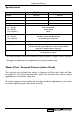
Operator’s Manual Specifications Profile Contour Height 985 mm 985 mm Depth 590 mm 590 mm Width 540 mm 660 mm Weight 105 kg 184 kg Electrical Services (i) Voltage (ii) Current (iii) Frequency Water Services (i) Pressure (ii) Stopcock Cup Capacity Cup Type Coin Mechanism 220 - 240 Volts AC 13 Amp Fused 50 Hz 100 Kpa (1 Bar) - 800 Kpa (8 Bar) 15 mm BSP from rising main 350 (when using 7oz squat cups) 7oz squat, 7oz tall and 9oz tall versions of the HIPS vending cup may be used although modifi
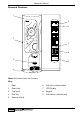
Operator’s Manual External Features 1 5 6 2 7 8 3 9 4 Note: Illustration shows the Contour. Key: 1. Door 6. Coin Entry (where fitted). 2. Door Lock 7. LCD Display 3. Cup Stand 8. Keypad 4. Drip Tray 9. Coin Return (where fitted) 5.
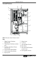
Operator’s Manual Internal Features 12 11 10 9 1 8 2 7 3 4 5 6 Note: Illustration shows Contour interior. Key: 1. Coffee Canister (Freshbrew machines only) 7. Mixing System 2. Coffee Brewer (Freshbrew machines only) 9. Large Ingredient Canister 3. Tea Brewer (Freshbrew Contour machines only) 4. Large Freshbrew Waste Bucket 5. Small Freshbrew Waste Bucket 6. Drip Tray Grill 6 8. Cup Turret 10. Door Switch 11. Filter Paper Roll (Freshbrew machines only) 12.
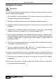
Operator’s Manual Installation Procedure Important! It is essential that personnel responsible for installing, commissioning and servicing the machine understand the following: 1. The installation and commissioning of the machine should only be carried out by trained and authorised service engineers. 2. All water and electrical services must be correctly and safely connected. 3. All covers should be replaced correctly and securely and the machine left in a safe condition. 4.
Operator’s Manual Connecting the Water Supply 1. The machine should be situated within 1 metre of a drinking water supply from a rising main, terminating with a W.R.C. approved 15mm compression stop tap. 2. The water supply should comply with both the Statutory Instrument No.1147 “Water, England and Wales” and The Water Supply (Water Quality) Regulations 1989.Water pressure at the stop tap must be within the limits 1 - 8 Bar (100 Kpa - 800 Kpa). 3.
Operator’s Manual Setting Up The following procedure must be carried out by a trained installation engineer before the machine can be used for the first time. 1. Ensure that the electrical and water services to the machine are connected correctly and turned on. Ensure that the waste tray is fitted correctly to the machine. 2. Open the front door of the machine. Insert the safety key supplied with the machine into the door switch.The machine is now on. 3.
Operator’s Manual Allow the cups to drop into the tubes directly from the packaging. DO NOT TOUCH THE CUPS WITH YOUR HANDS. Replace the cup turret lid. 8. Remove the ingredient canisters - DO NOT place ingredient canisters on the floor. Remove the lids from the ingredient canisters. Fill the canisters with the correct ingredients, re-fit the lids and re-fit canisters into machine. 9. Return the cup turret assembly to its operating position. Ensure that the unit locks into place.
Operator’s Manual How To Vend A Drink 1. Insert sufficient credit to cover cost of drink choice (where applicable). Press the number combination on the keypad for the drink of your choice followed by a strength option if required. 2. Cup will drop into the cup catcher and dispense head will move into dispense position. The drink will now be delivered into the cup. 3. The dispense head returns to its parked position and the display will tell you when your drink is ready.
Operator’s Manual Daily Cleaning and Re-filling The quality of drinks produced by Profile and Contour® machines can only be maintained if the machine is cleaned regularly following the schedule outlined.
Operator’s Manual 1. On arrival at the machine, open the door. Fill a cleaning bucket with hot water and dilute the bactericidal cleaner in accordance with the instructions on the product packaging. Swing the cup turret assembly out of the machine in order to gain access to the ingredient canisters. Remove the ingredient canisters. DO NOT PLACE THEM ON THE FLOOR. 2. Remove the canister shelf and extract tray. Using a dry brush, clean the area under the extract tray.
Operator’s Manual 5. Refit the whipper bases (a). Rotate the base anticlockwise to lock into position as shown. Refit the impeller's (b). Line up the dot on the impeller with the flat on the motor shaft. a b Refit mixing chambers, mixing bowls, steam hoods and dispense pipes. 6. Refit the dispense pipes to mixing chamber outlets. Refit the plastic dispense block to the dispense head assembly. Secure with the plastic thumb screw (a).
Operator’s Manual 9. Remove the drip tray from the machine. Empty and clean. Clean around the cup station area with a damp sanitised cloth. Wipe down the interior of the door. Clean the base, sides and back of the machine. Replace the drip tray. 10. Undo the thumb screws and remove cup throat complete with drain pipe (a). Clean cup throat and pipe in the sanitiser solution. Rinse components with clean water and dry thoroughly.
Operator’s Manual 13. Remove the coin mechanism cover (where fitted). Wipe the inside of the coin mechanism with a damp cloth. Check the coin tubes and refill as required. 14. Restore power to the machine using the safety key as shown in the illustration. Press the program entry switch, located in the switch panel on the rear of the door and enter the correct operator code - selection button 1 followed by 7.
Operator’s Manual Coffee Brewer Unit Maintenance At least twice a week the coffee brewer unit must be removed from freshbrew machines and cleaned. Safety First! Never clean or service the brewer unit while it is in motion as fingers may become trapped in the mechanism. Referring to the diagram, proceed as follows:1. Open the front door of the machine. Remove the paper/waste ingredient guard. 2. Switch on the power using the door switch safety key. 3.
Operator’s Manual Tea Pot Brewer Cleaning At the same time as the coffee brewer is being cleaned, the tea brewer (where fitted) should also be removed and cleaned. Safety First! Never clean or service the tea pot brewer unit while it is in motion as fingers may become trapped in the mechanism. Referring to the illustrations, proceed as follows:1. Remove the tea pot bowl and mounting bracket assembly from the machine.
Operator’s Manual Operator Functions Programming Mode To access the Programming mode you need to enter a sequence of key strokes on the front panel.The time between each key stroke must be less than 5 seconds otherwise the machine will return to standby mode. Once in Programming mode, there is no time constraint. Programming mode utilises the front panel keys, as defined in Figure 1, in order to enter values and commands.
Operator’s Manual Accessing the Programming Mode 1. Press the program entry switch, mounted in a panel inside the top of the door, followed by the Operator’s Access Code - selection button 1 followed by 7. Code entry errors may be erased using the cancel (C) key. 2. With the correct code entered the title of the first sub-program will be displayed on the LCD.The LCD will display the message: FOR SERVICE PRESS ACCESS 3. To step through the sub programs, press either the up (▲) or down (▼) keys. 4.
Operator’s Manual Function Switches Profile and Contour® machines are fitted with 3, two position rocker switches, mounted in a panel inside the top of the door. These switches are used for the following functions: Program Entry Switch This switch allows the operator to access the operator’s program. Once pressed, enter the Operator’s Access Code (selection button 1 followed by 7) from the keypad.
Operator’s Manual a. Open the front door of the machine and insert the safety key. b. Press and release the flush switch. c. Empty the waste tray when complete. Brewer Flush Switch (Freshbrew Models) 1. The brewer flush switch allows the brewer to be flushed independently. In order to guarantee the highest standards of cleanliness, the boiler fill valve is disabled, ensuring that the water used is delivered at the optimum temperature to kill any micro-organisms. 2.
Operator’s Manual Sub Programs The 10 sub programs within the Operator’s Program are shown in the following diagram - figure 2. Figure 2 To access a sub program within the Operator’s Program, enter the programming mode as described previously.To step through the sub programs, press either the up (▲) or down (▼) keys.To enter a displayed sub program, press the access key.
Operator’s Manual (c) Paper Feed: This function allows the operator to feed a new filter paper roll through the coffee brewer feed mechanism. (d) Brewer Flush: This function enables the brewer unit to be flushed independently. (e) Counter Reset: This function enables the operator to reset all vend/weight counters to zero.To reset the counters, press the access key.All counters are cleared at this point, the machine gives an intermittent beep and flashes the message: COUNTERS RESET to warn the operator.
Operator’s Manual 4. The = symbol changes to a > symbol indicating that it is now possible for new data to be entered. Key in the new price using the keypad and when correct press access to overwrite the old data. 5. The prices for other drinks can now be set following the sequence described in the previous “Programming Mode” section. Alternative Tariff 1 Sub-Program (Default = 15) This sub-program works in exactly the same way as the drink price sub program and has the same appearance.
Operator’s Manual 2. This is an empty price period.To enter a price period (e.g. 10:30 - 15:45,Tariff 2, Weekends), press access.The display will now read: START > 00:00 Note: The arrow symbol (>) indicates that it is possible to update the display. 3. Enter the correct start time in hours and minutes using buttons 0 - 9 on the keypad. Note: To correct any entry errors, press cancel to delete the last digit entered. Pressing cancel with no digits displayed will exit to the Operator’s program. 4.
Operator’s Manual Vend Counters Sub-Program 1. When the vend counters sub-program is entered, the first drink counter is displayed: COFFEE 1372 2. The up (▲) and down (▼) keys enable the counters for each drink to be viewed, and values noted, but they cannot be altered using the keypad.These counters can only be reset by using the ‘reset counters’ function within the “operations subprogram”. 3.
Operator’s Manual 3. To change the time shown, press the access key.The display will now show: TIME = XX:XX SET TIME > 00:00 4. Enter the correct time in hours and minutes using buttons 0 - 9 on the keypad. 5. When correct, press access. The time is now set. To view the date, press the up or down key until the display reads: DATE = XX:XX:XX where xx:xx:xx is the current date. 6. To change the date, press the access key.The display will now show: DATE = XX:XX:XX SET DATE > 00:00:00 7.
Operator’s Manual Jug Code Sub-Program 1. The jug code is a two digit security code that when entered correctly via the keypad, followed by a two digit drink selection number, allows a jug to be vended. Entry into the jug code sub program allows the operator to set a unique jug code. 2. Access the jug code and enter a new code using buttons 0-9 on the keypad. Press access to overwrite the old code.
Operator’s Manual Problem Solving In the unlikely event of the machine developing a problem, details are given in the table below (figure 3) on how to deal with common faults that can be easily remedied by the operator. Safety First! Should the remedy given below not cure the problem, or the fault is not listed, DO NOT ATTEMPT TO CURE THE FAULT YOURSELF. Contact your machine supplier for assistance.
Operator’s Manual Machine Leaking Should the machine develop a leak, switch off the mains water supply at the stop-tap and if safe to do so, switch off the mains electricity supply. Contact your machine supplier for further assistance. Safety First! Do not attempt to repair the machine yourself. De-Commissioning the Machine Should the machine need to be shut down for short periods, for example over a long weekend, no special treatment is required.
Operator’s Manual Recommended Spares List The spares items listed below are available from your machine supplier. 10 11 12 13 14 9 15 2 8 3 16 7 1 4 5 6 18 17 Ref. No. 1 2 3 4 5 6 7 8 9 10 11 12 13 14 32 Part No.
Operator’s Manual Ref. No. 15 16 17 18 Part No.
Operator’s Manual Notes 34
Operator’s Manual Notes 35
Operator’s Manual Notes 36
Pipsmore Park, Bumpers Farm Industrial Estate, Chippenham,Wiltshire SN14 6NQ Tel: +44 (0)1249 444807 Fax: +44 (0)1249 444819 Email: sales@cranems.co.uk Website: www.cranems.co.