With REMOTE II OPERATOR'S MANUAL Version (8.0) 20140630 LTD. 2117 East 5th Street Superior, WI 54880 USA tel: 715-398-3627 fax: 715-398-3279 www.cranesong.com © 2004, 2005, 2006, 2009, 2014 Crane Song, LTD. Subject to change without notice. the U.S.A.
First time power up Main Functions Talk back Gain Trims Shift Mode Headphone controls Output 3 mode select Surround mode Reboot Internal configuration jumpers Back panel Surround interconnect Remote control size Accessory connector Revision History 5.
IMPORTANT SAFETY INSTRUCTIONS 1. Read these instructions 2. Keep these instructions 3. Heed all warnings 4. Follow all instructions 5. Do not use this apparatus near water 6. Clean only with dry cloth 7. Install in accordance with the manufacturer's instructions 8. Do not install near any heat sources such as radiators, heat registers, stoves, or other apparatus (including amplifiers) that produce heat 9.
“Avocet” is designed to solve the problems of accurate monitoring and volume control as required by workstation users, studios and mastering rooms alike. Avocet is a stereo controller with three digital inputs, three analog inputs and a headphone system. All digital signals are up-sampled and jitter reduced to ensure highest accuracy during D/A conversion. Options are available to change the D/A mode, all though the default mode has been chosen as more accurate.
Notes: When configuring the units for Surround, if the system was not purchased as Surround please consult the factory This manual applies to Avocet version 1.
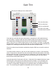
FIRST TIME POWER UP The first time that Avocet is powered up, it should be initialized. This is done by pushing all three output select buttons at the same time. This sets up the remote for proper operation. It also resets the user settings: All gains, main and phones are set to zero Output 1 is the selected output DAW is the input selected Phones are set to the Aux input Stereo speaker selection is selected All offsets are cleared The remote cable must be attached and screwed down before power up.
BUTTON FEEDBACK When holding down a button for gain trim; or speaker setup, the led now provides feedback that the button was held for the required time. The led will wink out for 1/2 second and then come back on. In the previous version there was no feedback to the user on mode change. This applies to the 6 input select buttons, the mono button, and the speaker buttons for selecting the mono output channel.
MAIN FUNCTIONS Truncates the digital input to 16 bits. For checking what 16 bits sounds like Channel Selection to 7.1 surround Talk back button sends the talk mic into the headphone output.
Talkback Operation Talk mic is on when the LED is on. It has push-on, push-off operation or latching. However if the talk button is held for one half second, talk back releases when the button is released, non latching The monitor level can be set when the talkback button is pushed. The monitors can be dimmed to off or a level that is below feedback. This will allow comminution in both directions while in talk mode.
Gain Trim Shift key to enable gain trim, offset control Gain trim offset clear Gain trim offset lock Gain trim unoffset lock must be in shift mode to enable these functions If one presses and holds the input select button a second time it will enable the input gain trim mode. It requires about one half second of hold time to enter the trim mode. Trim mode allows changing the input level on the selected input relative to all other inputs. Gain trim has an offset range of plus or minus 10 db in 1 db steps.
SHIFT MODE SETUP FUNCTIONS Changes DIM from relative LEVEL to absoulte LEVEL Changes output 3 to work in parallel with outputs 1 and 2 for use as a sub woofer output In the Shift Mode Select the source for the DAW input between AES, SPDIF, OPTICAL .
SHIFT MODE SETUP FUNCTIONS TALK BACK MIC GAIN TALK BACK MIC GAIN is changed by selecting the TALK button when in the SHIFT MODE. Turning the gain knob changes the mic gain.
SHIFT MODE Headphone Setup Headphones / shift to select phones control Dim Button over rides Headphone mode Headphone Level Selects direct AUX analog input for the Headphone output The headphone source is selected by the main input buttons. It’s level does not change with the main system level 13 The headphone source is selected by the main input buttons.
Shift Mode Output 3 Mode as sub woofer on-off With this button selected in the shift mode. OUT 3 is converted to work as a Sub Woofer output. It is full range unfiltered audio that can be turned ON or OFF with OUT 3. Thus allowing outputs 1and 3, or 2 and 3 to be on at the same time. If this is not selected, OUT 3 works as a normal third speaker system output Shift to select control Output 3 does not provide any filtering or mono summing.
In normal operation one should set the power amp gain, so that your normal listening level is with the gain knob at 1 o’clock. There is a supplied adjustable pad for powered monitors and power amps that have no gain control. Speaker selects - Mute and Solo Channel or speaker control is determained by the top row of buttons. The channel is on when the led is on. This applies to all modes of operation. The channels are Left, Right, Center, LFE, Surround Left, Surround Right, Extra Left, Extra Right.
Speaker select buttons now allow multiple selection at a time Mute will over ride all functions including Talk Back 16
Changing the speaker setup from Stereo to Surround Default mode By pressing any one of the speaker select buttons and holding it for about 0.5 seconds will put Avocet into the speaker set up mode. If SHIFT is selected the speaker setup is disallowed. Selecting the center channel button will cause the center channel be the mono speaker when selecting mono. This is the surround mode of operation Selecting the left, right, or both, (left and right) will disable the surround channels.
Speaker Setup Transparent Surround Mode In OUT 1 SETUP SELECT turning this button on will cause the unit to be in surround mode at all times (Transparent Surround `Mode) the mono speaker select function determines the active speakers when mono is selected MONO SPEAKER SELECT Selects which speaker is the mono output when mono is selected 18
Group Function This showes the key grouping The group function is reached by the phones / shift button and then selecting the group button.
Changing the speaker setup from Stereo to Surround By pressing any one of the speaker select buttons and holding it for 5 seconds will put Avocet into the speaker set up mode. Pressing the center channel button will make the center channel be the mono speaker when the mono function is selected.
Functions that can change There are trim pots on the back of the main unit for the analog gain trim. These have a range of 8 db There is a high gain mode selected by an internal jumper. This will add 14 db of gain to the Analog 2 input. There is a small pop that can be heard when the gain changes by 14 db.
Clearing the internal settings System Reset By pressing all three output selection buttons at the same time Avocet will reset all of it’s internal settings. This is the same as rebooting the remote.
Rev 8 D/A jumpers and Trims Main Audio Path Digital level trims Meter mute off = enabled on = disabled Meter level trims for digital metering output analog inputs only This jumper on for master or stereo operation It is on for a stereo system In a surround system this jumper in on, on the left right channels It is off on all other units.
REV 4 pcb Do not change jumpers or adjust the trim pots unless you are sure of what you are doing 24 JUMPER ON = STEREO, OFF = SURROUND OPERATION JUMPER ON THESE 2 METER = INPUT DEFAULT JUMPER ON THESE 2 METER = OUTPUT JUMPER ON SOLO = ANA1 INPUT JUMPER OFF SOLO = DAW INPUT JUMPERS FOR SURROUND OFF OFF - LEFT, RIGHT ON OFF - SURROUND LEFT, RIGHT OFF ON - CENTER REV 5 AND UP ONLY ON ON - EXTRA JUMPER FOR HIGH GAIN ON ANALOG 2 DEFAULT IS OFF LOW GAIN
REV 5 pcb Do not change jumpers or adjust the trim pots unless you are sure of what you are doing 25 JUMPER ON = STEREO, OFF = SURROUND OPERATION JUMPER ON THESE 2 METER = INPUT DEFAULT JUMPER ON THESE 2 METER = OUTPUT NOT ASSIGNED JUMPER ON SOLO = ANA1 INPUT JUMPER OFF SOLO = DAW INPUT JUMPERS FOR SURROUND OFF OFF - LEFT, RIGHT ON OFF - SURROUND LEFT, RIGHT OFF ON - CENTER REV 5 AND UP ONLY ON ON - EXTRA JUMPER FOR HIGH GAIN ON ANALOG 2 DEFAULT IS OFF LOW GAIN
REV 5 pcb Center Channel Jumpers Do not change jumpers or adjust the trim pots unless you are sure of what you are doing. This controls what happens with the center channel and LFE channel when in the mono mode. The settings below is for stereo operation, and in surround mode, the front and surround channels. Center Channel Surround The settings below is for LFE and center channel operation.
JUMPERS POSITIONS FOR STEREO OPERATION JUMPERS POSITIONS FOR SURROUND LEFT - RIGHT FRONT 27
JUMPERS POSITIONS FOR SURROUND CENTER - LFE JUMPERS POSITIONS FOR SURROUND LEFT - RIGHT SURROUNDS 28
JUMPERS POSITIONS FOR SURROUND EXTRA CHANNELS 29
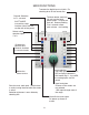
Analog inputs Digital inputs Analog input Gain Trims Analog Outputs Power Switch Second headphone output Analog Outputs Remote connector Power entry and fuse location
5.1 INTERCONNECT link cable Surround Left, Right channels Center = Left, LFE = Right Left and Right channels Connect Remote here When powering the system up. If they are not all powered at the same time, the audio box with the remote connected to it must be powered on last. If any of the units are not powered the remote will not work correctly. The internal jumpers must be set correctly.
STEREO INTERCONNECT Connect Remote here The internal jumpers must be set correctly.
8 inches 7.53 inches Depth not counting the knob is 1.62 inches PAD LOSS ADJUST INPUT OUTPUT XLR OUTPUT PAD This is an adjustable pad for use with amplifiers or powered monitors that have no gain control. The pad has a range of 6 to 20 db of loss.
ACCESSORY CONNECTOR 1 2 3 4 5 6 7 8 9 10 11 12 13 14 15 16 17 18 19 20 21 22 23 24 25 Right Channel Source Output gnd gnd talk mic output - When talk button is pushed (Mic Output) Right phones out (Line level phone bus) Left phones out (Line level phone bus) gnd / ground data I/O do not connect gnd gnd gnd Surround mono input 6 Surround mono input 5 Left Channel Source Output mono out talk command in - enable by tying to gnd mute+ mute-, solosolo+ used in surround wiring from left-right to center channel g
Revision History Rev3 main pcb Non Surround Remote This version will not upgrade to surround operation. New everything is required. This version has a db15 connector accessory on it’s back all others have a db 25 pin connector This is units with serial numbers to A682840 Rev4 main pcb Non Surround Remote The Rev 4 main boards will work for front or surround channels only.
D/A Converter Starting with Sn A682890 we switched to a new SRC in the D/A converter. This D/A is a big improvement in sound quality. This is an upgradable item. In units with serial numbers of A682840 and less it will require some soldering skills. The later units it is plugin. Upgrades Upgrades are factory direct only in the US and in the rest of the world by the local Crane Song distrubition company.
This page is being updated Sn for REMOTE II starts with AR684189 Sn for the main unit with the new D/A start with AM684259
5.1 interface cable wiring diagram If you wish to use any the other accessory connector connections such as the talk back command input, they should be connected to the left, right audio box connector.
This is avery good starting place for setting up sub woofers. One could go farther and use a RTA and experment and find the best place in the room for subwoofer placement. This was written by Bob Katz, www.digido.com and is used with permission Accurately Set Up a Subwoofer With (Almost) No Test Instruments Bass frequencies are extremely important to sound reproduction. Everyone is interested in getting their bass right, but most people haven’t a clue how to proceed.
range speaker instead of spikes. Whichever mounting method, the goal is to reduce sympathetic vibrations or traveling waves in cabinets, floor and walls. The resonant frequency of the box and stand should be extremely low. Hit the box with your fist and confirm it does not have a resonant character; sweep a sine wave through the system and listen for vibrations. I’ve had great success with a very thin isolator between the speaker and the stand which compresses almost completely under the speaker’s weight.
Polarity is not Phase This is still a confusing topic, perhaps because people are too timid to say polarity when they mean it. The polarity of a loudspeaker refers to whether the driver moves outward or inward with positive-going signal, and can be corrected by a simple wire reversal. Remember that phase means relative time; phase shift is actually a time delay.
All musical instruments and transducers produce harmonics as well as fundamentals. To the best of our ability to discriminate, we will be concentrating on the fundamental tones in this piece of music. If your loudspeakers have significant harmonic distortion, they can complicate or confuse the test. Many studio loudspeakers are designed for high power handling at the expense of tonal accuracy or distortion. This test is not for them.
contribution. Reverse the polarity of the sub. The polarity which produces the loudest bass is the correct polarity. Mark it on the plugs, and don’t forget it! Next comes an iterative process (“lather, rinse, repeat until clean”). Here’s a summary of the foursteps: (1, 2, & 3) Using filtered pink noise, we’ll determine the precise phase, amplitude and crossover dial position for any one crossover frequency. (4) Then we’ll put Rebecca back on and see if all the bass notes now sound equally loud.
More Refinement Fine tuning the stereo separation (space between the woofers) If you have stereo subwoofers, their left-right separation must be adjusted. Play Spanish Harlem. Listen to the sound of the bass with the subs off. It should be perfectly centered as a phantom image and and its apparent distance from the listener should subtend a line between the satellites. If it is not perfectly centered or its image is vague, the satellites are too far apart. Now add the subwoofers.
What To Do When the Results are Less Than Perfect When interpreting Spanish Harlem, don’t get too hung up on little “dips” in level. Dips are less objectionable to the ear than peaks. First, attack problems with resonant notes and then look at the dips. Everything may not be rosy the first time around. Supposing that the subwoofer helped the bottom note(s), which means the crossover is at the right frequency, but some upper note in the progression has been affected.
Acknowledgments: Jon Marovskis of Janis Subwoofers introduced me to the concept of a pitch detection technique many years ago. This article refines and expands onhis original idea. Many thanks to Dave Moulton for insightful technical and editorial comments. Also, thanks for manuscript review and suggestions by Johnson Knowles of the Russ Berger Design Group, Eric Bamberg, Greg Simmons and Steven W.Desper.
HEADPHONE SYSTEM Method 1 Seperate cue mix A external cue mix may be feed into the AUX analog input, the internal headphone amp system can be used AVOCET MAIN UNIT HEADPHONE CUE MIX Talk back mic Aux Analog input Headphone output on headphone jack Headphone output contains, the cue mix and the talk back mic To set this up select the PHONES / SHIFT button. When in this mode select the “phones / aux” button (this is the phones source), then adjust the phones level with the big knob.
Method 2 Seperate cue mix The phones are not effected by the main level The main audio source is feed to the internal headphone amp. AVOCET MAIN UNIT Talk back mic Headphone output on headphone jack Headphone output contains, the main audio source and the talk back mic To set this up select the PHONES / SHIFT button. When in this mode select the “phones / main” (this is the phones source), then adjust the phones level with the big knob.
Method 3 Seperate cue mix The phones are effected by the main level The main audio source is feed to the internal headphone amp. AVOCET MAIN UNIT Talk back mic Headphone output on headphone jack Headphone output contains, the main audio source and the talk back mic To set this up select the PHONES / SHIFT button. When in this mode select the “phones / pgm” (this is the phones source), then adjust the phones level with the big knob.
USING AN EXTERNAL HEADPHONE AMPLIFIER The audio source will be what ever has been defined during setup, see the pervious three pages. The headphone jack will still operate The external amplifer and the headphone jack will have the same audio and talk back mic singals. The external output level is also changed when changing the internal phones level.
EXTERNAL AUDIO OUTPUT The audio source will be the selected input It is not effected by the gain control or other functions DB 25 CONNECTOR 2 3 1 14 7 gnd gnd Right Audio Out Left Audio Out gnd / ground NOTE: all gnd / ground pins are the same Ground / Shield Audio Left Audio Right EXTERNAL AUDIO OUTPUT this followes the source and can be used for metering or other functions 51
SENDING THE TALK MIC SIGNAL TO AN EXTERNAL HEADPHONE SYSTEM The talk mic signal can be sent to an external headphone system as showen. The mic signal will be present only when the talk mic button is on.
Avocet alignment The alignment should not be changed unless you are 100 % positive that you know how to do this and have very good equipment. If not you could mess up the alignment, and the left - right channel balance. The gain trims will provide a plus or minus 3 db range, which can allow for different configurations. Do not attempt to adjust this as a way to reduce the output level. If you do you will mess it up. If you need to reduce the output level use the provided pads.
CK the stepped attenuator analog input 1 apply a square wave 5V p-p, 1KHz look at the output starting at max output check for level change in proper sequence anc correct wave shape If there is a problem at the max setting the other adjustments may have to be redone With 1 volt on ANA1 check, both inputs, the phones, main and mono outputs on the aux connector With PHONES MAIN selected and the phones gain at max mono = 1.
AES OUTPUT STEREO DIGITAL METER CABLE 5.