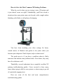
How to Solve the Most Common 3D Printing Problems What do you do when you are trying to run a 3D printer and it just doesn't come out right? Undoubtedly, you'll have faced a situation where your prints come out skewed, with a rough surface finishing, with blobs or with plenty of stringing. You have been tweaking your slicer settings for hours, wasted meters of filament and gotten to the point where you become quite desperate.
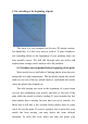
Print Quality Troubleshooting Guide This guide is a great place to start if you are trying to improve the quality of your 3D printed parts. We have compiled an extensive list of the most common 3D printing issues along with the software settings that you can use to solve them. Best of all, the guide uses a large collection of real-world images to make each issue easy to identify when examining your own 3D printed parts.
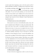
1: Not extruding at the beginning of print This issue is a very common one for new 3D printer owners, but thankfully, it is also very easy to resolve! If your extruder is not extruding plastic at the beginning of your printing, there are four possible causes. We will talk through each one below and explain what settings can be used to solve the problem. (1) Extruder was not primed before beginning of the print Most nozzle have a bad habit of leaking plastic when they are sitting idle at a high temperature.
extruder right before beginning a print so that the nozzle is full of plastic and ready to extrude. A common way to do this in Cura is by including something called skirt. The skirt will draw a circle around your part, and in the process, it will prime the extruder with plastic. If you need extra priming, you can increase the number of skirt outlines on the Additions tab in Cura.
then it is likely that your nozzle is clogged. This can happen if foreign debris is trapped inside the nozzle, when hot filament sits inside the nozzle too long, or if the thermal cooling for the nozzle is not sufficient and the filament begins to soften outside of the desired melt zone. Fixing a clogged nozzle may require disassembling the nozzle, so please contact your printer manufacturer before you proceed.
screws or knobs that control the position of the bed. If your printer has an adjustable bed and you’re having trouble getting your first layer to stick to the bed, the first thing you will want to verify is that your printer’s bed is flat and level. If the bed is not level, one side of your bed may be too close to the nozzle, while the other side is too far away. Achieving a perfect first layer requires a level print bed.
(3) First layer is printed too fast As you extrude the first layer of filament on top of the build platform, you want to make sure that filament can properly bond to the surface before starting the next layer. If you print the first layer too fast, the filament may not have time to bond to the build platform. For this reason, it is typically very useful to print the first layer at a slower speed so that the filament has time to bond to the bed. Cura provides a setting for this exact feature.
filament will tend to separate from the build platform as it cools. This is an important fact to keep in mind as you print your first layer. If you notice that the layer seems to stick initially, but later separates from the print bed as it cools, it is possible that your temperature and cooling settings are to blame. Many printers that are intended to print high-temperature materials like ABS include a heated bed to help combat these problems.
you are using ABS filament, it is common to disable the cooling fan for the entire print, so entering a single setpoint would suffice (Layer 1 at 0% fan speed). If you are working in a breezy environment, you may also want to try to insulate your printer to keep the wind away from your part. (5) The build platform surface (tape, glues, and materials) Different filaments tend to adhere better to different materials.
sticky substances tend to work very well if everything else has failed. Feel free to experiment to see what works best for you! (6) When all else fails: Brims and Rafts Sometimes you are printing a very small part that simply does not have enough surface area to stick to the build platform surface. Cura includes several options that can help increase this surface area to provide a larger surface to stick to the print bed. One of these options is called a “brim.
However, because the 3D printer does not provide any feedback about how much filament actually leaves the nozzle, it’s possible that there may be less filament exiting the nozzle than what the software expects (otherwise known as under-extrusion). If this happens, you may start to notice gaps between adjacent extrusions of each layer. The most reliable way to test whether or not your printer is extruding enough filament is to print a simple 20mm tall cube with at least 3 perimeter outlines.
under-extrusion issues, then you need to adjust your extrusion multiplier. This is a very useful setting in Cura that allows you to easily modify the amount of filament that is extruded (otherwise known as the flow rate). You can find this setting by clicking “Edit Process Settings” and going to the Extruder tab.
monitoring how much plastic is actually extruded. If your extrusion settings are not configured properly, the printer may extrude more plastic than the software expects. This overextrusion will result in excess plastic that can ruin the outer dimensions of your part. To resolve this issue, there are only a few settings you need to verify in Simplify3D. Please see the Underextrusion section for a more detailed description.
hollow, we want the exterior to remain solid. To do this, Simplify3D allows you to specify how many solid layers you want on the top and bottom of your part. For example, if you were printing a simple cube with 5 top and bottom solid layers, the software would print 5 completely solid layers at the top and bottom of the print, but everything else in the middle would be printed as a partially hollow layer.
achieve the same effect. If you are noticing gaps between the extrusions in your top surface, the first thing you should try is increasing the number of top solid layers. For example, if you noticed the problem using only 3 top solid layers, try printing with 5 top solid layers to see if the problem is improved. Note that additional solid layers will occur within your part dimension and do not add size to the exterior of your part.
means that your nozzle is not extruding as much plastic as the software expects. For a full description of this issue and how to correct it, please read the Not Extruding Enough Plastic section. 6:Stringing or Oozing Stringing (otherwise known as oozing, whiskers, or “hairy” prints) occurs when small strings of plastic are left behind on a 3D printed model. This is typically due to plastic oozing out of the nozzle while the extruder is moving to a new location.
important retraction settings as well as several other settings that can be used to combat stringing, such as the extruder temperature settings. (1) Retraction distance The most important retraction setting is the retraction distance. This determines how much plastic is pulled out of the nozzle. In general, the more plastic that is retracted from the nozzle, the less likely the nozzle is to ooze while moving. Most direct-drive extruders only require a retraction distance of 0.52.
vary depending on the material that you are using, so you may want to experiment to see if different speeds decrease the amount of stringing that you see. (3) Temperature is too high Once you have checked your retraction settings, the next most common cause for excessive stringing is the extruder temperature. If the temperature is too high, the plastic inside the nozzle will become less viscous and will leak out of the nozzle much more easily.
can automatically adjust the travel path to make sure that nozzle has a very short distance to travel over an open space. In fact, in many cases, the software may be able to find a travel path that avoids crossing an open space all together! This means that there is no possibility to create a string, because the nozzle will always be on top of the solid plastic and will never travel outside the part.
The plastic that exits your extruder may be anywhere from 190 to 310 degrees Celsius. While the plastic is still hot, it is pliable and can easily be formed into different shapes. However, as it cools, it quickly becomes solid and retains its shape. You need to achieve the correct balance between temperature and cooling so that your plastic can flow freely through the nozzle, but it can quickly solidify to maintain the exact dimensions of your 3D printed part.
aftermarket fan or using a small handheld fan to cool down the layers faster. (2) Printing at too high of a temperature If you are already using a cooling fan and you are still seeing this issue, you may want to try printing at a lower temperature. If the plastic is extruded at a lower temperature it will be able to solidify faster and retain its shape. Try lowering the print temperature by 5-10 degrees to see if it helps.
software to adjust the printing speed for layers that take less than 15 seconds to print, the program will automatically slow down the printing speed for these small layers. This is a vital feature for combating these overheating issues. (4) When all else fails: Try printing multiple parts at once If you have already tried the 3 items above and you are still having trouble achieving sufficient cooling, there’s one more thing you can try.
toolhead to a specific location, and hopes that it gets there. In most cases, this works fine because the stepper motors that drive the printer are quite powerful, and there are no significant loads to prevent the toolhead from moving. However, if something does go wrong, the printer would have no way to detect this. For example, if you happened to bump into your printer while it was printing, you might cause the toolhead to move to a new position.
either of those speeds are too high, it can cause shifting to occur. If you are comfortable adjusting more advanced settings, you may also want to consider lowering the acceleration settings in your printer’s firmware to provide a more gradual speed up and slow down. (2) Mechanical or Electrical Issue If the layer misalignment continues, even after reducing your print speed, then it is likely due to mechanical or electrical issues with the printer.
screw (otherwise known as a grub screw). These set-screws anchor the pulley to the shaft of the motor so that the two items spin together. However, if the set-screw loosens, the pulley will no longer rotate together with the motor shaft. This means that the motor may be spinning, but the pulley and belts are not moving. When this happens, the toolhead does not get to the desired location, which can impact the alignment of all future layers of the print.
Each successive layer is printed on top of the previous layer, and in the end this creates the desired 3D shape. However, for the final part to be strong and reliable, you need to make sure that each layer adequately bonds to the layer below it. If the layers do not bond together well enough, the final part may split or separate. We will examine several typical causes for this below and provide suggestions for resolving each one.
cold plastic. If you notice that your layers aren’t bonding together and you are certain that your layer height isn’t too large, then it is possible that your filament needs to be printed at a higher temperature to create a strong bond. For example, if you tried to print ABS plastic at 190℃, you would likely find that the layers of your part will easily break apart. This is because ABS typically needs to be printed around 220-235℃ to create a strong bond between the layers of your print.
spinning, it can grind away enough plastic from the filament so that there is nothing left for the gear teeth to grab on to. Many people refer to this situation as the filament being “stripped,” because too much plastic has been stripped away for the extruder to function correctly. If this is happening on your printer, you will typically see lots of small plastic shavings from the plastic that has been ground away.
If you continue to encounter filament grinding, even after increasing the temperature, then the next thing you should do is decrease the printing speed. By doing this, the extruder motor will not need to spin as fast, since the filament is extruded over a longer period of time. The slower rotation of the extruder motor can help avoid grinding issues. You can adjust this setting by clicking “Edit Process Settings” and selecting the Speeds tab.
where something goes wrong with this process and the extruder is no longer able to push plastic through the nozzle. These jams or clogs are usually due to something inside the nozzle that is blocking the plastic from freely extruding. While this may be daunting the first time it happens, but we will walk through several easy troubleshooting steps that can be used to fix a jammed nozzle.
through the nozzle, then it’s likely you will need to clean out the nozzle before proceeding. Many users have had success heating their extruder to 100℃ and then manually pulling the filament out (hopefully along with any debris that was inside!). Others prefer to use the needle push the material backwards through the nozzle tip. There are plenty of other methods and each extruder is different, so please consult your printer manufacturer for precise instructions.
(2) The filament has stripped against the drive gear During a print, the extruder motor is constantly spinning trying to push the filament into the nozzle so that your printer can keep extruding plastic. If you try to print too quickly or you try to extrude too much plastic, this motor may end up grinding away the filament until there is nothing left for the drive gear to grab onto. If your extruder motor is spinning, but the filament is not moving, then this is likely the cause.
extruder toolhead, but the extruder motor will not be moving at all. The only way to resolve this issue is to turn off the printer and allow the electronics to cool down. You may also want to add an extra cooling fan if the problem continues. 13.Weak Infill The infill inside your 3D printed part plays a very important role in the overall strength of your model.
others. For example, Grid, Triangular, and Solid Honeycomb are all strong infill patterns. Other patterns like Rectilinear and Fast Honeycomb may sacrifice some strength for faster printing speeds. If you are having trouble producing strong reliable infill, try a different pattern to see if it makes a difference. (2) Lower the print speed The infill is typically printed faster than any other portion of your 3D print.
the Infill tab. The “Infill Extrusion Width” is set as a percentage of the normal extrusion width. For example, if you enter a value of 200%, the infill extrusions will be twice as thick as the outline perimeters. One thing to keep in mind when adjusting this setting is that the software must also maintain the infill percentage that you specify. So if you set the infill extrusion width to 200%, the infill will use twice as much plastic for each line.
location when the entire shell had been printed. These marks are commonly referred to as blobs or zits. As you can imagine, it is difficult to join two pieces of plastic together without leaving any mark whatsoever, but there are several tools in Simplify3D that can be used to minimize the appearance of these surface blemishes.
appears when the extruder initially begins printing the perimeter. If the defect does not occur until the end of the perimeter when the extruder is coming to a stop, then there is a different setting to adjust. This setting is called coasting. You can find it right below the retraction settings on the Extruder tab. Coasting will turn off your extruder a short distance before the end of the perimeter to relieve the pressure that is built up within the nozzle.
and won’t be visible from the outside. For this reason, many printers will have the “Only retract when crossing open spaces” option enabled to avoid unnecessary retractions. Another related setting can be found in the “Movement Behavior” section. If your printer is only going to retract when crossing open spaces, then it would be beneficial to avoid these open spaces as much as possible.
point. Next, go to the Advanced tab and enable the option labeled “Perform retraction during wipe movement”. This will prevent a stationary retraction, since the printer has now been instructed to wipe the nozzle while it retracts. This is a very powerful feature and a great option to try if you are still having trouble removing these defects from the surface of your print.
Each layer of your 3D printed part is created using a combination of outline perimeters and infill. The perimeters trace the outline of your part creating a strong and accurate exterior. The infill is printed inside of these perimeters to make up the remainder of the layer. The infill typically uses a fast back-andforth pattern to allow for quick printing speeds.
the outlines. However, if the infill is printed too fast, it will not have enough time to bond to the outline perimeters. If you have tried increasing the outline overlap, but you are still seeing gaps between your perimeters and infill, then you should try decreasing the print speed. To do this, click “Edit Process Settings” and select the Speeds tab. Adjust the “Default Printing Speed”, which controls the speed of any movements where the extruder is actively extruding plastic.
noticing the curling at the very beginning of your print, please see the Print Not Sticking to the Bed section to address first layer issues. 15:Scars on Top Surface One of the benefits of 3D printing is that each part is constructed one layer at a time. This means that for each individual layer, the nozzle can freely move to any portion of your print bed, since the part is still being constructed down below.
when the nozzle tries to move across each layer, it may drag through some of the excess plastic. Before you look at any other settings, you should make sure that you are not extruding too much plastic. Please read the Extruding Too Much Plastic section for more details. (2) Vertical lift (Z-hop) If you know you are extruding the correct amount of plastic, but are still having trouble with the nozzle dragging across your top surface, then it might be worth looking at the vertical lift settings in Simplify3D.
16:Holes and Gaps in Floor Corners When building a 3D printed part, each layer relies on the foundation from the layer below. However, the amount of plastic that is used for the print is also a concern, so a balance must be achieved between the strength of the foundation and the amount of plastic that is used. If the foundation is not strong enough, you will start to see holes and gaps between the layers.
“Edit Process Settings” and click on the Layer tab. For example, if you were previously printing with two perimeters, try the same print with four perimeters to see if the gaps disappear. (2) Not enough top solid layers Another common cause for a weak foundation is not having enough solid layers for the top surfaces of your print. A thin ceiling will not be able to adequately support the structures that are printed on top of them.
The sides of your 3D printed part are composed of hundreds of individual layers. If things are working properly, these layers will appear to be a single, smooth surface. However, if something goes wrong with just one of these layers, it is usually clearly visible from the outside of the print. These improper layers may appear to look like lines or ridges on the sides of your part. Many times the defects will appear to be cyclical, meaning that the lines appear in a repeating pattern (i.e.
frequently cyclical, meaning that the temperature will vary with a sine wave pattern. As the temperature gets hotter, the plastic may flow differently than when it is cooler. This will cause the layers of the print to extrude differently, creating visible ridges on the sides of your print. A properly tuned printer should be able to maintain the extruder temperature within +/-2 degrees. During your print, you can use Simplify3D’s machine control panel to monitor the temperature of your extruder.
18:Vibrations and Ringing Ringing is a wavy pattern that may appear on the surface of your print due to printer vibrations or wobbling. Typically, you will notice this pattern when the extruder is making a sudden direction change, such as near a sharp corner. For example, if you were printing a 20mm cube, each time the extruder changes to printing a different face of the cube, it would need to change directions.
the second controls the speed of rapid movements where no plastic is being extruded. You may need to adjust both settings to see an effect. (2) Firmware acceleration The firmware that runs on your 3D printer’s electronics typically implements acceleration controls to help prevent sudden direction changes. The acceleration settings will cause the printer to slowly ramp up in speed and then to slowly decelerate before changing directions. This functionality is vital for preventing ringing.
19:Gaps in Thin Walls Because your 3D printer includes a fixed size nozzle, you may encounter issues when printing very thin walls that are only a few times larger than the nozzle diameter. For example, if you were trying to print a 1.0mm thick wall with a 0.4mm extrusion width, you may need to make some adjustments to ensure your printer creates a completely solid wall and does not leave a gap in the middle.
pass. To enable this option, change the Internal Thin Wall Type to “Allow single extrusion fill”. This will use a dynamic single extrusion that will adjust in size to perfectly fill the gap between these walls. For more information about single extrusion options,click here to view our detailed article on the subject. (2) Change the extrusion width to fit better In some cases, you may find that you have better luck changing the size of the plastic that is extruded from the nozzle.
thin features that are smaller than the nozzle size. For example, if you were trying to print a 0.2mm thick wall with a 0.4mm diameter nozzle, you may notice that this thin wall does not show up in the Simplify3D preview. If you frequently need to print extremely thin features, we will explain the best options to consider for these micro-sized prints. (1) Enable single extrusion walls Simplify3D includes a specialty printing mode specifically for very thin walls and exterior features.
model. For example, it may be a part that someone else designed or one that you downloaded from the internet. In this case, you may want to consider obtaining a second nozzle for your 3D printer that allows it to print smaller features. Many printers have a removable nozzle tip, which makes these aftermarket adjustments quite easy. For example, many users purchase a 0.3mm nozzle as well as a 0.5mm nozzle to provide two options.
The first thing you should check is the spool of plastic that is feeding into your printer. You need to make sure that this spool is able to rotate freely and that the plastic is easily being unwound from the spool. If the filament becomes tangled, or the spool has too much resistance to spin freely, it will impact how evenly the evenly the filament is extruded through the nozzle.
low layer height, such as 0.01mm, there is very little room for the plastic to exit the nozzle. This gap below the nozzle is only 0.01mm tall, which means that the plastic may have a difficult time exiting the extruder. Double check to make sure you are using a reasonable layer height for your printer. You can view this setting by clicking “Edit Process Settings” and selecting the Layer tab. If you are printing at a very small layer height, try increasing the value to see if the problem goes away.
inconsistent extrusion. Finally, many plastics also have a tendency to degrade over time. For example, PLA tends to absorb moisture from the air, and over time, this will cause the print quality to degrade. This is why many spools of plastic include a desiccant in the packaging to help remove any moisture from the spool. If you think your filament may be at fault, try swapping the spool for a new, unopened, high-quality spool to see if the problem goes away.
As you start printing larger models, you may start to notice that even though the first few layers of your part successfully adhered to the bed, later on the part begins to curl and deform. This curling can be so severe that it actually causes part of your model to separate from the bed, and may cause the entire print to eventually fail. This behavior is particular common when printing very large or very long parts with high temperature materials such as ABS.
for parts that tend to warp. For this reason, many users prefer to disable any external cooling fans entirely when printing with materials such as ABS. This allows all of the layers to stay warm for a longer period of time, increasing your chance of success. You can verify your fan speed settings by clicking on the Cooling tab of your process settings in Simplify3D.
23:Poor Surface Above Supports One of the major benefits of Simplify3D is the ability to create innovative support structures which allow you to create incredibly complex parts that would be hard to manufacture otherwise. For example, if you have a steep overhang or part of your model with nothing below it, then a support structure can provide a foundation for these layers. The support structures created by Simplify3D are disposable and can be easily separated from the final part.
performance may improve to 60 degrees if you lower your layer height to 0.1mm. This has the obvious advantage of decreasing your print time and reducing the amount of support structures required for the print, but it will also allow you to create a smoother surface on the underside of your parts. If you find that you need to increase the print quality in this area, this is one of the first settings you will want to adjust.
Vertical Separation Layers. This setting determines how many empty layers are left between the support structures and the part. For example, if you are printing your support structures with the same material as your part, it is common to use at least 1-2 vertical separation layers. Otherwise, if you used 0 separation layers and you are printing everything with the same material, the supports may bond to the part and can become difficult to remove.
using a different material for the support structures, you can frequently decrease your Upper Vertical Separation Layers to zero, and reduce your Horizontal Offset from the part to around 0.1mm. If you are interested in learning more about this technique, you can watch a more detailed video about the process here. 24:Dimensional Accuracy The dimensional accuracy of your 3D printed parts can be extremely important if you are creating large assemblies or parts that need to precisely fit together.
Future layers can also be affected by the extra plastic on this layer, which creates several oversized layers at the bottom of the part. So before you spend too much time trying to perfect the dimensional accuracy of your prints, you need to verify that your measurements are not being affected by the first layer position. One common way to do this is by printing a model with 50-100 layers and then only measuring the top 20 or so layers.
offset the edges of your print to account for these differences. This setting is labeled “Horizontal size compensation” and can be found on the Other tab of your Process Settings. For example, setting this value to -0.1mm will shrink your model by 0.1mm in the X and Y directions. This setting works best when the dimensional error is consistent, even when printing models of different sizes. For example, if the part is always 0.
25:Poor Bridging Bridging is a term that refers to plastic that needs to be extruded between two points without any support from below. For larger bridges, you may need to add support structures, but short bridges can typically be printed without any supports to save material and print time. When you are bridging between two points, the plastic will be extruded across the gap and then quickly cooled to create a solid connection.
see bridging extrusions and verify that these lines are shown in yellow. If the bridging area is not shown in yellow, there are a two settings you will want to check. Exit the preview, click “Edit Process Settings”, and go to the Other tab to view your Bridging settings. The first option in this section is the “Unsupported area threshold”. This allows the software to ignore very small bridging areas and focus on the larger bridging regions that may need special settings.
happen automatically. If you ever want to try a different infill angle for these bridging layers, you can also do this by enabling the “Use fixed bridging angle” option in your process settings. (3) Adjust settings for optimal performance The bridging regions in Simplify3D are printed with special extrusion, speed, and cooling settings to achieve optimal performance. The extrusion and speed adjustments for these regions can be found on the Other tab of your process settings.
enable support generation for the entire model, or use Simplify3D’s customizable support structures for extra control. Please see this video for more details about using custom support structures.