
Instructions / Assembly

DISC SWING
Blue Sky Play PT 1208 7-21-2016
2700 Riverside Drive For Customer Service, Call: 844-801-5828
Chattanooga, TN 37406
Specications subject to change without notice.
Manufactured for Blue Sky Play
Made in China
BP 012
Installation Instructions:
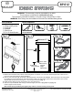
1. Measure and mark the center, bottom of the swing beam a minimum of 21’’ from the nearest support and a minimum of 9’’
from end of the swing beam as shown in (Fig. 1).
2. Drill one 3/8’’ hole up through the bottom of the swing beam at the mark made in Step 1. Attach the rope to the swing beam
by installing the eye bolt through the hole and securing it with a 3/8’’ at washer and lock nut. Place a bolt cover over the
exposed bolt end and secure it using two 1-1/4’’ screws, as shown in (Fig. 1).
3. Adjust the Disc Swing so that it is a minimum of 8” from the ground.
4. Tie knot in rope underneath Disc Swing to maintain height, as shown in (Fig. 3a) through (Fig. 3c).
Pull knot tight to ensure security.
Note: Check knots periodically throughout play season to ensure security of swing seat.
(1) Disc Swing
(1) Rope with Eye Bolt
(1) Lock Nut
(1) Washer
(1) Bolt Cover
(2) 1-1/4’’ Wood Screws
Tools Required:
TAPE MEASURE DRILL BITS
PHILLIPS
3/8’’ (9,5MM)
9/16’’ SOCKET AND
SOCKET WRENCH
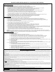
WARNING: This accessory must be assembled by an adult.
This accessory is intended for residential use only.
This accessory intended for children 3-10 years of age. Weight Limit: 115 lbs.
WARNING: Disc Swing must be installed on the end of an extended Swing Beam.
Kit Contents:
swing beam
barrote del columpio
poutre à balançoire
Minimum 21’’ to
set support
Bolt Cover
1-1/4’’ Screws
Loc Nut
Washer
Minimum 9’’ to end
of beam
Minimum 9’’
8”
Minimum
From Ground
Minimum 21’’
Fig. 3a
Fig. 3b
Fig. 3c
swing beam
barrote del columpio
poutre à balançoire
Minimum 21’’ to
set support
Bolt Cover
1-1/4’’ Screws
Loc Nut
Washer
Minimum 9’’ to end
of beam
Minimum 9’’
8”
Minimum
From Ground
Minimum 21’’
Fig. 3a
Fig. 3b
Fig. 3c
swing beam
barrote del columpio
poutre à balançoire
Minimum 21’’ to
set support
Bolt Cover
1-1/4’’ Screws
Loc Nut
Washer
Minimum 9’’ to end
of beam
Minimum 9’’
8”
Minimum
From Ground
Minimum 21’’
Fig. 3a
Fig. 3b
Fig. 3c
Fig. 1 Fig. 2 Fig. 3a
Fig. 3b
Fig. 3c
DISC SWING
Knot under
Disc Swing
used for
height
adjustment.