
User's Manual


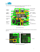


Table Of Contents

The adaptor board AB has two interfaces. The 30-pin FFC connector interfaces the IB. The 26-
pin FFC connector interfaces the 3141 130 0034.1. This is shown in figure 1.2d.
3141 130 0034.1 Interface
IB Interface
Figure 1.2d Adapter Board
1.3 Powered by Battery Pack (May Not Be Included)
DC 5V
The evaluation board can also be powered by a 4-AA
battery pack (NiCd, NiMH or Alkaline or normal) as
shown in figure 1.3.
The plug is configured as a standard DC jack with outer
rim (5.2mm) to Ground (-) and inner rim (2.6mm) to DC
5V (+).
Figure 1.3 4-AA Battery Pack
1.4 USB-RS232 Serial Cable (May Not Be Included)
If you have a RS232 serial-serial cable and your
notebook/PC has a RS232 serial port, you do not need a
USB-RS232 serial cable.
The evaluation kit does not include a USB-RS232 serial
cable that would be required to configure the evaluation
boards with the desired CU or MU settings in GUI. You
have to provide this cable as shown in figure 1.4.
Figure 1.4 USB-RS232 Serial Cable
6