i le STORAGE SO! ME Ron ae le GE Model: QGDSKSAO01 Weather Guard / Knack 420 E. Terra Gotta Ave Crystal Lake, IL 60014 USA Weather Guard / Knack 185A Courtney park Drive East Mississauga, ON L5T 276 800-456-7865 Toll Free 800-334-2081 Fax Knaack.OrderEntry @ catercorner 888-562-2251 Toll Free 888-456-8460 Fax Knaack.OrderEntry.Canada @catercorner Part No. 24-0326 Hev.
ENGLISH Foo weather guard, ATTENTION: PLEASE READ AND UNDERSTAND ALL INSTRUCTIONS AND WARNINGS BEFORE ASSEMBLING, INSTALLING OR USING THIS PRODUCT.
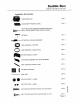
Saddle Box USER INSTRUCTIONS Installation Kit Includes: SYSTEM MODULE QTY. 1 QUICKDRAW™ REMOTE (FOB) Quivery WEATHER GUARD EXTREME PROTECTION®LOCK Bee QTY. 2 -CLIPS, GASKETS AND KEYS INCLUDED = ANTENNA ary. 1 1 ——c> ACTUATOR & LINKAGE ASSEMBLY ary. i & WIRE HARNESS BATTERY QTY. 1 OO WIRE HARNESS SADDLE BOX QTY. 1 am SYSTEM MODULE COVER aTv. i wy ACTUATOR ASSEMBLY MOUNTING BRACKET ary. ~~ WIRE HARNESS COVER PLATE ’ ’ Qry.d i ADHESIVE SQUARES QTY. 8 emu WIRE TIES QTY.
ENGLISH pinfeather guard, Contents 1. SYSTEM MAINTENANCE Il. MAXIMIZE THE PERFORMANCE OF YOUR SYSTEM 1Il. QUICK DRAW SADDLE BOX COMPATIBILITY. IV. MECHANICAL ASSEMBLY AND INSTALLATION V. INSTALLING QUICK DRAW SYSTEM MODULE VI. SYSTEM CHECK Vii. FINAL INSTALLATION VIII. OPERATING INSTRUCTIONS FOR REMOTE CONTROL (FOB) IX. PAIRING THE FOB TO THE QUICK DRAW SYSTEM | i FCC ID: ‘Tho label information is also included fo the user manual.
#” Saddle Box USER INSTRUCTIONS FCC&IC FCC&IC Caution: This device complies with Part 15 of the FCC Rules and Canada license-exempt RS-210 standard. Operation is subject to the following two conditions: (1) THIS DEVICE MAY NOT CAUSE HARMFUL INTERFERENCE (2) THIS DEVICE MUST ACCEPT ANY INTERFERENCE RECEIVED, INCLUDING INTERFERENCE THAT MAY CAUSE UNDESIRED OPERATION.
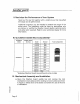
ENGLISH impeacher gar, ll. Maximize the Performance of Your System Never put the key fob together with a cellphone as this may affect the range and its performance. Additions! antennas can be installed to extend the range of the active zone. The installation must be done by technicians who are trained or certified by Weather Guard dealers (optional parts and extra labor required). Refer to your authorized dealer for more information. ill.
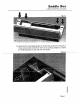
Saddle Box USER INSTRUCTIONS b. Remove the lock retaining clips for both locks as shown in Figure 2. Then remove both locks from the box by palling straight out. Save the retaining clips for use with the new locks.
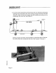
ENGLISH weather guard, ¢. Run the ful] size saddle box wire harness (with four (4) total connectors) starting from the driver side and running through the lock box and along the front of the box through the latch plates and ending at the passenger side lock box. See Figure 3 som Figure 3 mo] TOP VIEW actuator perm nll 20m 2900 The four (4) pin connector should remain on the driver side of the box. Do not tie down the shames at this time. See Figures 3 through 7.
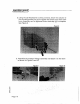
Saddle Box USER INSTRUCTIONS Feed the harness from driver to passenger site through the two latch plates } Figure 6 d. Remove the bolts from the passenger side latch as shown in Figure 7.
ENGLISH weather ward, e. Using the (3) M3.9x25mm screws provided, attach the actuator to the mounting bracket, but do not tighten the screws more than a few turns. Assembly can be tightened down once step (g) is complete. See Figure 8. Figure 8 Ll f. Assemble the actuator linkage assembly and attach it to the larch as shown in Figures 9 and 10. .
Saddle Box USER INSTRUCTIONS a. Complete actuator and bracket assembly installation. See Figure 1. 1. Tighten the (3) screws holding the actuator to the bracket all the way down. 2. Bolt the bracket and larch back to the box using the original bolts. Be careful not to over frighten. See Figure 11. h. Plug the actuator connector into the main saddle box wire harness. See Figure 11. Figure 11 i. Install the new locks with switches and wire harnesses attached.
ENGLISH gatherer war, V.
Sadie Box USER INSTRUCTIONS b. Place the Quick Draw system module on the driver side of the box, but do not fasten in place. See Figure 16. Figure 16 ¢. Plug the saddle box harness into the system module using the four (4) pin connector. Plug into the connector labeled saddle box per system module diagram. d. Using locking rod cover plate (removed in step a.
ENGLISH [weather guard) e. Attach the (4) pin connector on the battery harness fo the system module and feed the other end of the harness out of the box through the hole in the box partition, down the inside of the gas strut guard and exit the box through the 12v access grommet hole located on the driver side end of the box. See Figure 18. Run the shames to the truck battery and cut to length. Crimp the proper size ring terminal fo each wire and apply heat to the insulation to shrink tight to the wires.
Saddle Box USER INSTRUCTIONS b. Test 2: Push Button Remote Operation 1. Ensure truck box lid is closed and all push button locks are in locked position, and Quick Draw FOB is within 100 ft of the truck. 2. Test Quick Draw push bunion remote function by depressing and holding button 1. » If ruck box opens correctly, proceed with final installation steps.
d. Replace both lock mechanism cover plates and both locking rod cover plates (driver side has antenna mounted to it.
Sadie Box USER INSTRUCTIONS VIII. Operating Instructions for Remote Control (FOB) Your Quick Draw Remote comes equipped with dual-mode Functionality: PKE & RKE a. Proximity Key less Entry (PKE) “Hands-Free” Mode. 1 Directional Transmitter (inside truck box) communicates with FOB 2. Transmitter range has foot Range” from the saddle bax 3. When box is in locked position, user can open box by depressing one of the extreme protection® lock buttons. | Figure 22 b.
ENGLISH weather guard, IX. Pairing the FOB to the Quick Draw System NOTE: FOB memory is cleared every time the system begins learning mode. In this case, all corresponding Fobs will need to be re~paired by following sequence below. The Quick Draw FOB comes per-paired to the system module. Repairing of the Fobs to ihe system module will be required in the following scenarios: When adding additional Fobs or if the module is accidentally put into learning mode. a.
Saddle Box USER INSTRUCTIONS 1. FOB 1: perform steps 1-4 above for first FOB 2. Fob 2 through 10: perform mass steps 1-4 within 30 seconds of each other urinal all Fobs have been paired 3. System will automatically exit learning made within 30 seconds d. Additional features The FOR bunions can be programmed to work in one of three ways: 1, Single press Press FOB button once fo open desired box 2. Double click Press FOB button quickly twice 3.
ENGLISH weather guard, Any modification or ui ride product shall immediately void all manufacturers warranties. Manufacturer disclaims ail liability for injuries to persons or property resulting from any modification to, or unintended use of this produce.
Saddle Box USER INSTRUCTIONS Notification Procedures if the WEATHER GUARD? Product doss net confirm with the farms of this limited warranty, the original owner must promptly nosily the Manufacturer in writing upon discover af the nonconformity. In order to receive the remedies under this limited warranty, the warranty claim must describe the nature of the nonconformity, and a copy of ihe original sales receipt, invoice, bill or other proof of purchase must accompany the claim.
Knickknack ATTN: Warranty Claims 420 E. Terra Gotta Avenue Crystal Lake, IL 60014 www.knaack.com IF you have any questions, please call oll free at 1-800-456-7656. ©2013 Knack LLC A (EE TE) CORNER' GMT BPOE Serest Co.