DTT 3500 Digital User Guide On-line Version
Safety & Regulatory Information The following sections contain notices for various countries: Notice for the USA Modifications FCC Part 15: This equipment has been tested and found to comply with the limits for a Class B digital device, pursuant to Part 15 of the FCC Rules. These limits are designed to provide reasonable protection against harmful interference in a residential installation.
IMPORTANT SAFETY INSTRUCTIONS READ INSTRUCTIONS – All safety and operating instructions should be read before the product is operated. RETAIN INSTRUCTIONS – The safety and operating instructions should be retained for future reference. HEED WARNINGS – All warnings on the product and in the operating instructions should be adhered to. FOLLOW INSTRUCTIONS – All operating and use instructions should be followed. CLEANING – Unplug this product from the wall outlet or other power source before cleaning.
Contents DTT3500 Digital Introduction......................................................................................................... 1 Inventory ............................................................................................................ 2 Recommended Signal Sources ........................................................................... 2 Installation Sequence.........................................................................................
Introduction T hank you for purchasing DTT3500 Digital by Cambridge SoundWorks. DTT3500 Digital lets you experience the full potential of Dolby ® Digital multichannel sound from your DVD player or game console, with a dynamic output that rivals a component home theater system. It processes both Dolby Digital and Dolby Surround program material. DTT3500 Digital includes an OPTICAL connection to enhance the connectivity and usability to any devices with OPTICAL output.
Inventory Recommended Signal Sources Examine each unit carefully for shipping damage. If there is any, do not install or use the system. For advice, call the store where you made your purchase or call Creative Technology Ltd. technical support. Save the shipping carton and inserts in case you have to transport the system later. All of the items shown in the illustration below should be included with your system. If anything is missing, notify the retailer.
Installation Sequence Speaker System Connections 1. Read all of the instructions before installing the speaker system. 2. Attach the provided stand to the Decoder Amplifier if you wish to place the unit vertically. For more details see “Decoder Amplifier Placement” on page 12. 3. Connect the Satellites, Center Speaker, and Subwoofer to the Decoder Amplifier. 4. Connect the Dolby Digital output of your digital program source to the coaxial and/or optical Dolby Digital input of the Decoder Amplifier. 5.
Speaker System Connection Diagram Front Right Satellite Rear Right Satellite Center Speaker Front Left Satellite Rear Left Satellite Power Adapter Subwoofer 4
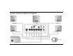
Signal Source Connections Dolby Digital source For devices with optical output Connect the Dolby Digital/SPDIF output of your signal source to the Decoder Amplifier’s Dolby Digital (AC3) / PCM Audio Inputs COAXIAL or OPTICAL jack using the SPDIF Cable (RCA to RCA) or the Optical Cable. Connect the optical output of these devices (e.g. CD or MD players) to the OPTICAL input with the Optical Cable. Game consoles Connect the optical output of the game console (e.g.
Signal Source Connection Diagram Dual Female-to-Female RCA DIGITAL OUT Red White Stereo to Dual RCA Cable SPDIF Cable (RCA to RCA) Game Console Digital Output (Eg. PC-DVD Encore) LINE OUT 4-Ch Sound Card Output (Eg. Sound Blaster Live!) OPTICAL OUTPUT LINE OUT REAR OUT Lime-Green 2-Ch Sound Card Output (Eg. Sound Blaster AWE64) Black Lime-Green Optical Cable COAXIAL OUTPUT Tandem Audio Cable DIGITAL OUT OR Digital Output (Sound Blaster 5.
Speaker Cable and Stand Installation Speaker Cable Installation Typically, the 3 meter (5 feet) Speaker Cables will connect the front Satellites and the Center Speaker to the Decoder Amplifier and the 5 meter (9 feet) Speaker Cables will connect the rear Satellites to the Decoder Amplifier. A panel of twelve selfadhesive labels is provided to identify each Satellite and Subwoofer and the opposite end of the cable connected to a Satellite and Subwoofer. 1. Identify a 3 meter Speaker Cable.
Center Speaker Stand Installation Unlike the Desktop Stand (for Satellites), the stands for the Center Speaker are of the screw-in type. 1. Align the Attachment Arm to the Center Speaker (see Diagram B). 2. Use the screw provided to connect the Attachment Arm to the Center Speaker. Mounting Speakers B Screw Mounting Attachment Arm Mounting the rear satellites on side walls will give you superior surround effects.
Speaker Placement The Front Satellites The left front and right front Satellites play stereo music, the offscreen sounds of video playback and the front channels of 4-channel games. These Satellites should be placed to the sides of your T.V. or monitor. Try to form an equilateral triangle with your head and the satellites (see Diagram D). Be sure to have a clear line of sight from your listening position to these Satellites.
The Rear Satellites The rear Satellites provide the surround effects in Dolby Digital, Dolby Surround or Creative Multi Speaker Surround modes. They also produce the discrete rear sounds of 4channel sound cards. 5 meters (16 feet) of cable is provided with the two remaining Satellites for more flexibility in rear channel placement. The rear Satellites may be placed in any convenient sites alongside the listener, including sites slightly forward of the listening location.
The Subwoofer The Subwoofer’s optimum position is on the floor against the wall. The closer the Subwoofer is to a corner, the stronger the maximum bass output. We strongly recommend placing the Subwoofer on the floor (see Diagram J). Leave at least 5 cm (2 inches) of space between the Subwoofer face and a wall. Position the Subwoofer so that it’s connection panel is facing a wall, shielded from inadvertent contact.
Decoder Amplifier Placement The Decoder Amplifier can be placed on the desktop, a shelf or any site that makes the controls convenient. The Power Adapter cord must be able to reach from the Decoder Amplifier back panel to your AC power receptacle. Place the Decoder Amplifier on a hard, flat surface. There are ventilation slots on the Decoder Amplifier’s enclosure. Do not block these ventilation slots by placing materials over them.
Decoder Amplifier Functions The Standby LED lights up when the Power Adapter is connected to the mains. Press the Power button to turn on the Decoder Amplifier. The CMSS Music LED will remain illuminated after initial start-up. The last used CMSS mode’s light will illuminate for subsequent start-ups from system standby mode. The Optical LED also lights up after initial start-up. The last used Dolby Digital/PCM Audio input’s light will illuminate for subsequent start-ups from system standby mode.
MUSIC: Creates a 5.1 speaker soundfield appropriate for music from any analog sound source. FOURPOINT/5.1 DIN: Use this mode for DVD games having Dolby Digital soundtracks with EAX or Microsoft DirectSound3D for real-time positioning of sound effects. Typically a Dolby Digital 5.1-channel + analog signal source. If a signal source is connected to the Analog Line In minijacks, 4.1-channel output is produced. If the signal source is connected to the Digital DIN input, up to 5.1-channel output is produced.
(which provide a fixed “reference” output level). All functions except for the level controls are disabled while the test sound is running. The speaker level controls operate at all times. If desired, you may adjust these controls during program material to finetune the balance. (This function is only available on the Remote Control) Note: Volume levels during the test sequence are lower than during normal operation. 12.
CD-ROMs and CDs with Dolby Surround encoding will feature the Dolby Surround logo at the beginning of the program or on the packaging. Process these programs by selecting Analog In using the Dolby Pro Logic button for input through Analog Line In. If using Digital DIN input, ensure that the Digital DIN on the Dolby Digital/PCM Audio input is selected. Then select Digital In using the Dolby Prologic button. When Dolby Pro Logic is selected CMSS is turned off.
Multiple Connections Monitor Game Console PC RF to VGA converter box Video Signal VGA switch box Audio Signal Connecting to a Game Console and a PC You can connect your game console and PC to the DTT3500 Digital system while sharing one monitor by following the instructions below. Audio Connection: 1. Connect your game console’s audio output to the Decoder Amplifier’s Front minijack input with the provided Dual Femaleto-Female RCA adapter. 2. Connect your PC’s audio output to the Decoder Amplifier.
Applications Guide Playing Games: Playing Multi-format DVD Games These games have Dolby Digital or Dolby Pro Logic movie clips mixed with the actual game sequence. These DVD games have a mix of Dolby Digital 5.1 sound (a digital signal at the SPDIF input) and soundcard wavetable output (a signal at the analog input). PC-DVD Setup For AC-3 signal source connected to COAXIAL input: Select the COAXIAL input using the DOLBY DIGITAL/PCM AUDIO input selection button.
Using set-top DVD player or PlayStation2 Select OPTICAL or COAXIAL using the DOLBY DIGITAL/PCM AUDIO input selection button. For movies with Dolby Digital (AC3) soundtracks This signal is detected automatically and the DOLBY DIGITAL LED lights up. You will experience Dolby Digital 5.1-channel output. For 2-channel movies which are Dolby Surround-encoded carried within the Dolby Digital compressed bitstream The Dolby Pro Logic decoder will automatically decode the program for 5.1-channel movie experience.
CD Audio Music Karaoke Music Enjoying CD Audio on PC 1. Select LINE IN or DIGITAL DIN input using the MULTI-CHANNEL button. 2. Select the Music mode by pressing the CMSS button until the LED for Music mode lights up. This mode creates an enveloping five-speaker surround effect that enhances stereo music. Singing Karaoke on PC with Sound Blaster Live! only (with Creative PlayCenter) 1. Select LINE IN or DIGITAL DIN input using the MULTI-CHANNEL button. 2.
Important! Specifications EAX Playback Levels DTT3500 Digital 6-Channel Amplifier EAX is a collection of powerful, innovative audio technologies. Developed by Creative's world-class audio scientists and built into groundbreaking Personal Digital Entertainment (PDE) solutions, EAX is changing the way you experience audio. EAX offers advanced, interactive audio and high-definition sound to a new generation of portable audio appliances, audio applications, and internet services.
1-Year Limited Warranty T o the original purchaser, Cambridge SoundWorks, Inc. will warrant the speaker system to be free of defects in material and workmanship for a period of one (1) year from date of purchase. With respect to defects, Cambridge SoundWorks will, at its option, replace the product or repair the defect in the product with no charge to the original purchaser for parts or labor.