
Specifications
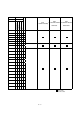
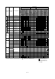
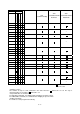
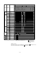

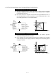
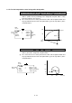
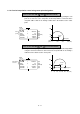
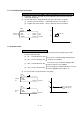
Table Of Contents
- Coverpage
- Safety Instructions
- Revision History
- Contents
- Introduction
- 1 Outline
- 2 Explanation of Functions
- 3 Q-PLC Multi-CPU
- 4 Q Motion CPU
- 5 SFC Program
- 6 SV22 Servo Programs
- 6.1 Servo program
- 6.1.1 Servo program configuration
- 6.1.2 List of servo commands
- 6.1.3 Linear control
- 6.1.4 Circular interpolation control using auxiliary point designation
- 6.1.5 Circular interpolation control using radius designation
- 6.1.6 Circular interpolation control using center point designation
- 6.1.7 Fixed-dimension feed control
- 6.1.8 Speed control
- 6.1.9 Speed/position changeover control
- 6.1.10 Speed changeover control
- 6.1.11 Constant-speed control
- 6.1.12 Repeated control (for speed changeover control and uniform speed control)
- 6.1.13 Simultaneous start
- 6.1.14 Zero point return
- 6.1.15 Position follow-up control
- 6.1.16 High-speed oscillation control
- 6.1.17 Helical interpolation control with auxiliary point designated
- 6.1.18 Helical interpolation control with radius designated
- 6.1.19 Helical interpolation control with center point designated
- 6.1.20 Current value change
- 6.1 Servo program
- 7 Operation Control Program
- 8 Windows Personal Computer Operations
- 9 Basic Practice Using the SV22 Real Mode
- 10 Applied Practice with SV22 Real Mode
- 10.1 Details of practice
- 10.2 Q172CPU practice machine system configuration
- 10.3 Practice SFC programs
- 10.4 Writing to the motion CPU
- 10.5 Program for operation
- 10.5.1 JOG operation
- 10.5.2 Main routine SFC program (real mode operation)
- 10.5.3 Execution of servo program (motion control step)
- 10.5.4 Stopping
- 10.5.5 Error reset
- 10.5.6 Current value change
- 10.5.7 Speed change (CHGV)
- 10.5.8 Reading actual current value
- 10.5.9 Continuous positioning
- 10.5.10 M code function
- 10.5.11 Indirect setting of servo program address
- 10.6 Operating the practice machine
- 11 Practicing with the SV22 Virtual Mode
- 11.1 Mechanism program
- 11.2 Details of practice
- 11.3 Starting up SW3RN-CAMP and creating the cam
- 11.4 SFC program for virtual mode
- 11.5 Editing the mechanism
- 11.6 Writing to the motion CPU
- 11.7 Reading of sequence program from Q-PLC CPU
- 11.8 SFC program for practice
- 11.9 Practice machine operations
- 11.10 Exercise (Roller setting)
- Appendix

6 - 12
6.1.7 Fixed-dimension feed control
1-axis to 3-axis control with FEED-1, FEED-2 and FEED3 (incremental method)
(1) Positioning control is executed for the designated movement amount from the
current stop position (0).
(2) The travel direction is designated by the sign of the travel value, as follows:
(a) Positive movement amount .... Forward direction (increased address)
(b) Negative movement amount ... Reverse direction (decreased address)
100
50
0
0 50 100 150 (mm)
1,
2,
30000.0
20000.0
5000.00
REAL
<K 58>
FEED-2
AXIS
AXIS
SPEED
Movement
amount
(µm)
(µm)
(mm/min)
Start point
End point
6.1.8 Speed control
1-axis control with VF, VR, VVF, VVR
(1) After the servomotor is started, control is carried out at the designated speed until
the stop command is input.
(a) VF ......Forward direction start
(b) VR......Reverse direction start
(c) VVF....Forward direction start
(d) VVR ...Reverse direction start
(2) The current value remains 0 and does not change.
1
2500.00
(mm/min)
1
2500.00
(mm/min)
200
100
0
0
100
200
300
(mm)
50
REAL
<K 30>
VF
AXIS
SPEED
Forward
run
Start point
Dose not stop until
the STOP signal is
input
REAL
<K 31>
VF
AXIS
SPEED
Reverse
run
Executes the control including position loop for
control of servo amplifier.
Executes the speed control excluding position
loop for control of servo amplifier.
Consequently, the deviation will not be excessive,
and it is applicable to the stopper, etc.