
Specifications
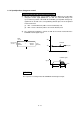
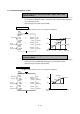
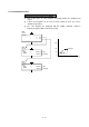
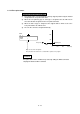
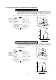
Table Of Contents
- Coverpage
- Safety Instructions
- Revision History
- Contents
- Introduction
- 1 Outline
- 2 Explanation of Functions
- 3 Q-PLC Multi-CPU
- 4 Q Motion CPU
- 5 SFC Program
- 6 SV22 Servo Programs
- 6.1 Servo program
- 6.1.1 Servo program configuration
- 6.1.2 List of servo commands
- 6.1.3 Linear control
- 6.1.4 Circular interpolation control using auxiliary point designation
- 6.1.5 Circular interpolation control using radius designation
- 6.1.6 Circular interpolation control using center point designation
- 6.1.7 Fixed-dimension feed control
- 6.1.8 Speed control
- 6.1.9 Speed/position changeover control
- 6.1.10 Speed changeover control
- 6.1.11 Constant-speed control
- 6.1.12 Repeated control (for speed changeover control and uniform speed control)
- 6.1.13 Simultaneous start
- 6.1.14 Zero point return
- 6.1.15 Position follow-up control
- 6.1.16 High-speed oscillation control
- 6.1.17 Helical interpolation control with auxiliary point designated
- 6.1.18 Helical interpolation control with radius designated
- 6.1.19 Helical interpolation control with center point designated
- 6.1.20 Current value change
- 6.1 Servo program
- 7 Operation Control Program
- 8 Windows Personal Computer Operations
- 9 Basic Practice Using the SV22 Real Mode
- 10 Applied Practice with SV22 Real Mode
- 10.1 Details of practice
- 10.2 Q172CPU practice machine system configuration
- 10.3 Practice SFC programs
- 10.4 Writing to the motion CPU
- 10.5 Program for operation
- 10.5.1 JOG operation
- 10.5.2 Main routine SFC program (real mode operation)
- 10.5.3 Execution of servo program (motion control step)
- 10.5.4 Stopping
- 10.5.5 Error reset
- 10.5.6 Current value change
- 10.5.7 Speed change (CHGV)
- 10.5.8 Reading actual current value
- 10.5.9 Continuous positioning
- 10.5.10 M code function
- 10.5.11 Indirect setting of servo program address
- 10.6 Operating the practice machine
- 11 Practicing with the SV22 Virtual Mode
- 11.1 Mechanism program
- 11.2 Details of practice
- 11.3 Starting up SW3RN-CAMP and creating the cam
- 11.4 SFC program for virtual mode
- 11.5 Editing the mechanism
- 11.6 Writing to the motion CPU
- 11.7 Reading of sequence program from Q-PLC CPU
- 11.8 SFC program for practice
- 11.9 Practice machine operations
- 11.10 Exercise (Roller setting)
- Appendix
6 - 14
6.1.10 Speed changeover control
1-axis to 3-axis control using VSTART, ABS-1, ABS-2, ABS-3, VEND
(absolute method)
(1) Using the currently stopped address, having the zero point as the reference as
the start point, positioning control is carried out to the end point while relaying the
speed changeover point.
(Speed changeover point is only for VABS)
Absolute method
An address that results in reverse run cannot be designated.
1,
2,
1,
1,
300000.0
200000.0
300.00
100000.0
1000.00
200000.0
5000.00
(µm)
(µm)
(mm/min)
(µm)
(mm/min)
(µm)
(mm/min)
200
100
0
0 100 200 300 (mm)
1000
5000
300
(mm/min)
REAL
<K 59>
VSTART
ABS-2
AXIS
AXIS
SPEED
VABS
AXIS
SPEED
VABS
AXIS
SPEED
VEND
End point
Start
point
End point
Speed
change point
Speed
change point
Speed changeover point
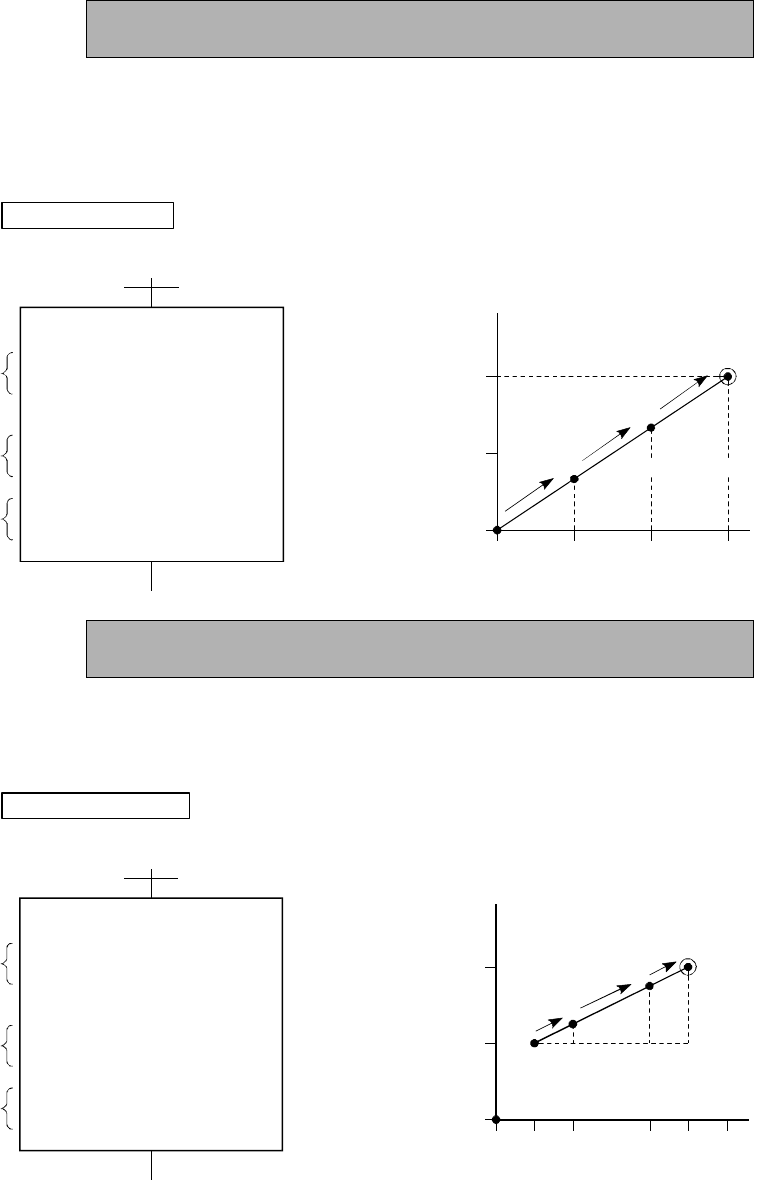
1-axis to 3-axis control using VSTART, INC-1, INC-2, INC-3, VEND
(increment method)
(1) Using the currently stopped address as the start point (0,0), positioning control is
carried out to the end point while relaying the speed changeover point.
(Speed changeover point is only for VINC)
Increment method
An address that results in reverse run cannot be designated.
1,
2,
1,
1,
200000.0
100000.0
300.00
50000.0
1000.00
100000.0
5000.00
200
100
0
0 100 200 300 (mm)
1000
5000
300
50 250
(mm/min)
REAL
<K 60>
VSTART
INC-2
AXIS
AXIS
SPEED
VINC
AXIS
SPEED
VINC
AXIS
SPEED
VEND
Movement
amount
Start
point
End point
Speed
change point
Speed
change point
(µm)
(µm)
(mm/min)
(µm)
(mm/min)
(µm)
(mm/min)