
Specifications

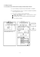
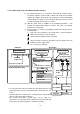
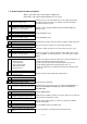

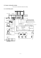

Table Of Contents
- Coverpage
- Safety Instructions
- Revision History
- Contents
- Introduction
- 1 Outline
- 2 Explanation of Functions
- 3 Q-PLC Multi-CPU
- 4 Q Motion CPU
- 5 SFC Program
- 6 SV22 Servo Programs
- 6.1 Servo program
- 6.1.1 Servo program configuration
- 6.1.2 List of servo commands
- 6.1.3 Linear control
- 6.1.4 Circular interpolation control using auxiliary point designation
- 6.1.5 Circular interpolation control using radius designation
- 6.1.6 Circular interpolation control using center point designation
- 6.1.7 Fixed-dimension feed control
- 6.1.8 Speed control
- 6.1.9 Speed/position changeover control
- 6.1.10 Speed changeover control
- 6.1.11 Constant-speed control
- 6.1.12 Repeated control (for speed changeover control and uniform speed control)
- 6.1.13 Simultaneous start
- 6.1.14 Zero point return
- 6.1.15 Position follow-up control
- 6.1.16 High-speed oscillation control
- 6.1.17 Helical interpolation control with auxiliary point designated
- 6.1.18 Helical interpolation control with radius designated
- 6.1.19 Helical interpolation control with center point designated
- 6.1.20 Current value change
- 6.1 Servo program
- 7 Operation Control Program
- 8 Windows Personal Computer Operations
- 9 Basic Practice Using the SV22 Real Mode
- 10 Applied Practice with SV22 Real Mode
- 10.1 Details of practice
- 10.2 Q172CPU practice machine system configuration
- 10.3 Practice SFC programs
- 10.4 Writing to the motion CPU
- 10.5 Program for operation
- 10.5.1 JOG operation
- 10.5.2 Main routine SFC program (real mode operation)
- 10.5.3 Execution of servo program (motion control step)
- 10.5.4 Stopping
- 10.5.5 Error reset
- 10.5.6 Current value change
- 10.5.7 Speed change (CHGV)
- 10.5.8 Reading actual current value
- 10.5.9 Continuous positioning
- 10.5.10 M code function
- 10.5.11 Indirect setting of servo program address
- 10.6 Operating the practice machine
- 11 Practicing with the SV22 Virtual Mode
- 11.1 Mechanism program
- 11.2 Details of practice
- 11.3 Starting up SW3RN-CAMP and creating the cam
- 11.4 SFC program for virtual mode
- 11.5 Editing the mechanism
- 11.6 Writing to the motion CPU
- 11.7 Reading of sequence program from Q-PLC CPU
- 11.8 SFC program for practice
- 11.9 Practice machine operations
- 11.10 Exercise (Roller setting)
- Appendix
1 - 2
(7) Operating system (OS) can be changed
Software packages to match applications are available, and by directly writing the
optical OS (refer to comparison table in section 2.1) into the CPU's built-in flash
memory, a motion controller matching each machine can be created.
This system is also compatible with software package function upgrades.
1) SV13 for transfer assembly
Using the dedicated servo commands, 1 to 4-axis linear interpolation, 2-axis
circular interpolation, 3-axis helical interpolation, CP control (uniform speed
control), speed control and position follow-up control can be carried out,
making this system suitable for applications such as transfer machines and
assembly machines.
Order control is enabled with SFC.
2) SV22 for automatic machine
Multiple servomotors can be simultaneously controlled with the mechanical
support language, and cam control can be carried out with the software. This
is suitable for applications such as automatic machines.
(8) Software cam ... Valid only with SV22
When the cam mechanism, often used in machine mechanisms is replaced with a
virtual mode cam for servomotor control, the following features can be realized.
1) Cam curve data can be created easily with the cam curve creation software
package, thereby eliminating the need to manufacture cam parts.
2) The cam can be replaced easily by changing the cam No. in the motion SFC
program.
3) There is no need to consider wear and life unique to the cam.
(9) Mechanism support language (Mechanism program) ... Valid only with SV22
Conventionally, synchronous operation and coordinated operation were required
for industrial machines and automatic machines, and as a means to achieve this,
each operation was mechanically connected.
With this method, the output mechanisms such as the rotation operation, linear
operation, reciprocating operation and feed operation, are operated from the main
shaft, which is the drive source, using a conveyance mechanism such as gears, a
clutch or crank. Although accurate synchronization operation and coordinate
operations are possible, this method lacks flexibility.
The mechanical support language frees the system from the conventional
mechanical connection, and allows the positioning control functions and
performance to be improved because the servomotor is controlled by processing
the machine mechanism movements with software. At the same time, this is an
electrical method, so there are few limitations to the mechanism and rational
designs can be made.
The system from the main shaft to the conveyance mechanism such as the gears,
clutch, reduction gears or differential gears, to the output mechanism such as the
roller output, ball screw output, rotary table output or cam output are described
with figures on the peripheral device screen. Just by setting each module
parameter, the synchronized operation and coordinate operation can be realized
and a flexible control system can be easily structured.
Thus, machine parts such as the main shaft, gears, clutch, crank, reduction gears,
differential gears and cam can be greatly reduced or omitted, allowing costs to be
reduced and wear to be eliminated.