
Specifications
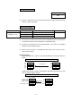
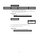
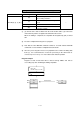
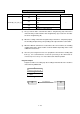
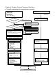
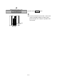
Table Of Contents
- Coverpage
- Safety Instructions
- Revision History
- Contents
- Introduction
- 1 Outline
- 2 Explanation of Functions
- 3 Q-PLC Multi-CPU
- 4 Q Motion CPU
- 5 SFC Program
- 6 SV22 Servo Programs
- 6.1 Servo program
- 6.1.1 Servo program configuration
- 6.1.2 List of servo commands
- 6.1.3 Linear control
- 6.1.4 Circular interpolation control using auxiliary point designation
- 6.1.5 Circular interpolation control using radius designation
- 6.1.6 Circular interpolation control using center point designation
- 6.1.7 Fixed-dimension feed control
- 6.1.8 Speed control
- 6.1.9 Speed/position changeover control
- 6.1.10 Speed changeover control
- 6.1.11 Constant-speed control
- 6.1.12 Repeated control (for speed changeover control and uniform speed control)
- 6.1.13 Simultaneous start
- 6.1.14 Zero point return
- 6.1.15 Position follow-up control
- 6.1.16 High-speed oscillation control
- 6.1.17 Helical interpolation control with auxiliary point designated
- 6.1.18 Helical interpolation control with radius designated
- 6.1.19 Helical interpolation control with center point designated
- 6.1.20 Current value change
- 6.1 Servo program
- 7 Operation Control Program
- 8 Windows Personal Computer Operations
- 9 Basic Practice Using the SV22 Real Mode
- 10 Applied Practice with SV22 Real Mode
- 10.1 Details of practice
- 10.2 Q172CPU practice machine system configuration
- 10.3 Practice SFC programs
- 10.4 Writing to the motion CPU
- 10.5 Program for operation
- 10.5.1 JOG operation
- 10.5.2 Main routine SFC program (real mode operation)
- 10.5.3 Execution of servo program (motion control step)
- 10.5.4 Stopping
- 10.5.5 Error reset
- 10.5.6 Current value change
- 10.5.7 Speed change (CHGV)
- 10.5.8 Reading actual current value
- 10.5.9 Continuous positioning
- 10.5.10 M code function
- 10.5.11 Indirect setting of servo program address
- 10.6 Operating the practice machine
- 11 Practicing with the SV22 Virtual Mode
- 11.1 Mechanism program
- 11.2 Details of practice
- 11.3 Starting up SW3RN-CAMP and creating the cam
- 11.4 SFC program for virtual mode
- 11.5 Editing the mechanism
- 11.6 Writing to the motion CPU
- 11.7 Reading of sequence program from Q-PLC CPU
- 11.8 SFC program for practice
- 11.9 Practice machine operations
- 11.10 Exercise (Roller setting)
- Appendix
7 - 7
Non-processing: NOP
Format
NOP
(1) Since the command is a non-processing command, and will not bring about any
influence upon last operation.
Block transfer: BMOV
Format Setting data Contents Result data type
(D) Head No. of transfer destination device
(S) Head No. of transfer source device
BMOV (D), (S), (n)
(n) Number of words transferred
–
(1) The contents of n-words from the word device designated by (S) are transferred in
a batch to the n-words from the word device designated by (D).
(2) The data can be transferred even when the transfer source device is overlapped
with the transfer destination device.
(3) When the Nn (cam No.) is designated in (D) and (S), the cam data can be
transferred in a batch.
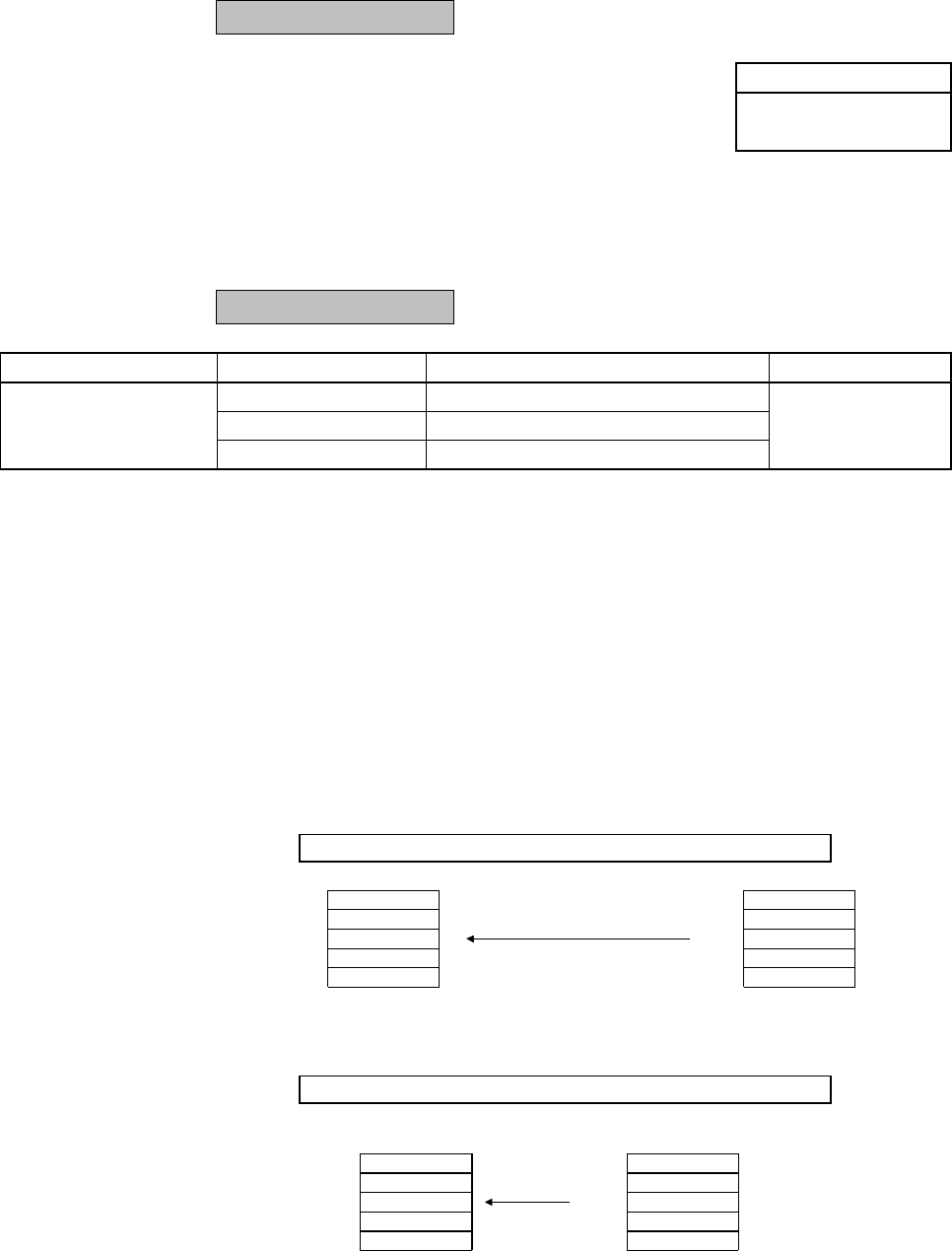
Program example
Program to transfer the contents of 5 words (from D0) to 5 words (from #10) in a
batch
BMOV #10, D0, K5
Batch transfer
12
34
56
78
90
D0
D1
D2
D3
D4
12
34
56
78
90
#10
#11
#12
#13
#14
Program to transfer the contents of 2,048 words (from #0) to the data area of cam
No.2 (resolution: 2048) in a batch
BMOV N2, #0, K2048
0th stroke ratio
1st stroke ratio
2nd stroke ratio
:
2047th stroke ratio
H0000
H0005
H000A
:
H0000
Data of cam No.2
H0000
H0005
H000A
:
H0000
#0
#1
#2
:
#2047
Batch transfer