
Specifications
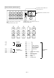
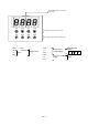
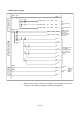
Table Of Contents
- Coverpage
- Safety Instructions
- Revision History
- Contents
- Introduction
- 1 Outline
- 2 Explanation of Functions
- 3 Q-PLC Multi-CPU
- 4 Q Motion CPU
- 5 SFC Program
- 6 SV22 Servo Programs
- 6.1 Servo program
- 6.1.1 Servo program configuration
- 6.1.2 List of servo commands
- 6.1.3 Linear control
- 6.1.4 Circular interpolation control using auxiliary point designation
- 6.1.5 Circular interpolation control using radius designation
- 6.1.6 Circular interpolation control using center point designation
- 6.1.7 Fixed-dimension feed control
- 6.1.8 Speed control
- 6.1.9 Speed/position changeover control
- 6.1.10 Speed changeover control
- 6.1.11 Constant-speed control
- 6.1.12 Repeated control (for speed changeover control and uniform speed control)
- 6.1.13 Simultaneous start
- 6.1.14 Zero point return
- 6.1.15 Position follow-up control
- 6.1.16 High-speed oscillation control
- 6.1.17 Helical interpolation control with auxiliary point designated
- 6.1.18 Helical interpolation control with radius designated
- 6.1.19 Helical interpolation control with center point designated
- 6.1.20 Current value change
- 6.1 Servo program
- 7 Operation Control Program
- 8 Windows Personal Computer Operations
- 9 Basic Practice Using the SV22 Real Mode
- 10 Applied Practice with SV22 Real Mode
- 10.1 Details of practice
- 10.2 Q172CPU practice machine system configuration
- 10.3 Practice SFC programs
- 10.4 Writing to the motion CPU
- 10.5 Program for operation
- 10.5.1 JOG operation
- 10.5.2 Main routine SFC program (real mode operation)
- 10.5.3 Execution of servo program (motion control step)
- 10.5.4 Stopping
- 10.5.5 Error reset
- 10.5.6 Current value change
- 10.5.7 Speed change (CHGV)
- 10.5.8 Reading actual current value
- 10.5.9 Continuous positioning
- 10.5.10 M code function
- 10.5.11 Indirect setting of servo program address
- 10.6 Operating the practice machine
- 11 Practicing with the SV22 Virtual Mode
- 11.1 Mechanism program
- 11.2 Details of practice
- 11.3 Starting up SW3RN-CAMP and creating the cam
- 11.4 SFC program for virtual mode
- 11.5 Editing the mechanism
- 11.6 Writing to the motion CPU
- 11.7 Reading of sequence program from Q-PLC CPU
- 11.8 SFC program for practice
- 11.9 Practice machine operations
- 11.10 Exercise (Roller setting)
- Appendix
10 - 10
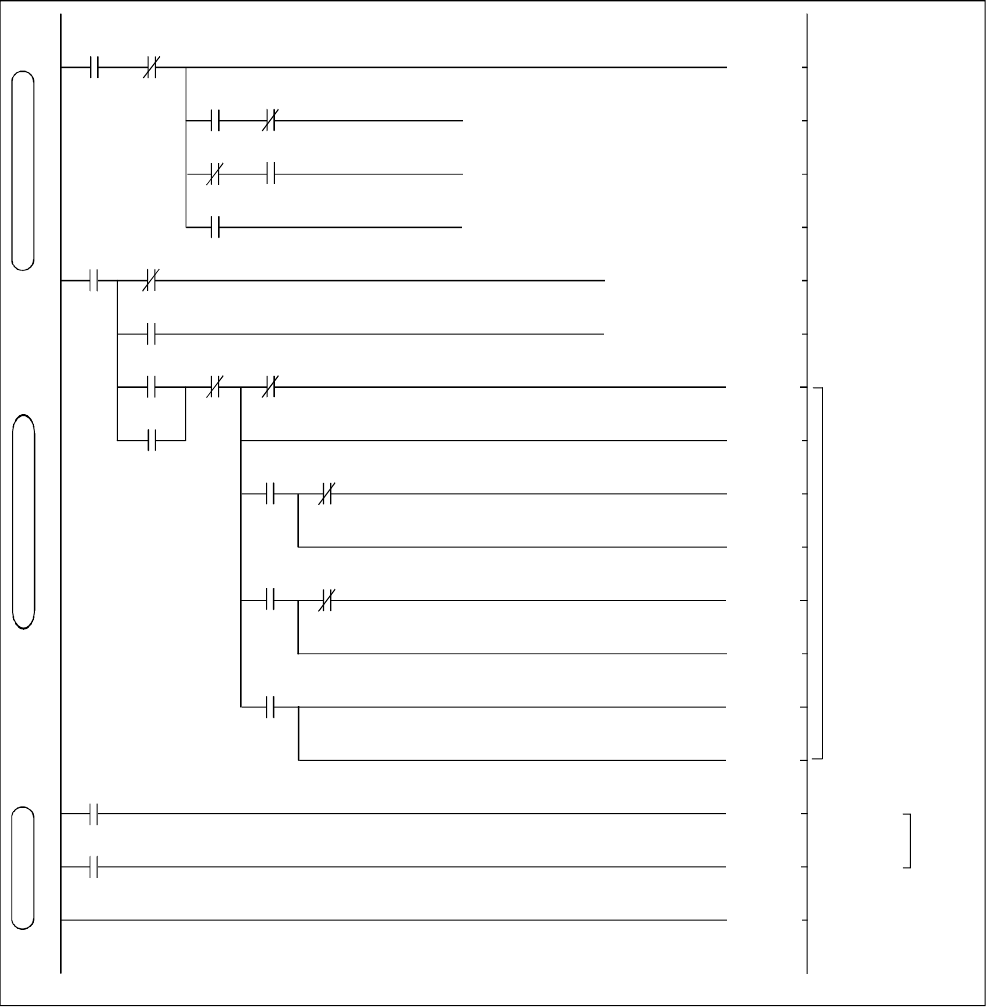
• Q02H sequence program
*1 When the clock relay is refreshed for automatic refresh operation, it may not be
refreshed at correct timing depending on automatic refresh timing.
M200 M201
[SP.SFCS H3E1 K130 M802 D802 ]
[SP.SFCS H3E1 K0 M801 D801 ]
[SP.SFCS H3E1 K10 M800 D800 ]
[DBCD D6004 K4Y20 ]
(M84 )
[DBCD D6006 K4Y20 ]
(Y30 )
(T0 )
(Y31 )
(T1 )
(Y32 )
(T2 )
(Y33 )
(T3 )
(M31 )
(M33 )
[END ]
X18
X19
X18 X19
X1A
SM400
X20
X20
M205
M206
T3 T0
T0
T1
T1
T2
T2
SM412
SM413
96
0
41
94
92
K5
K5
K5
K5
SFC program start
Actual current value display
Clock output
Start of JOG mode
SFC
Start of real mode
SFC
Start of virtual mode
SFC
Output of 1-axis
current value as
BCD code
Output of 2-axis
current value as
BCD code
The lamps (Y30 to
Y33) turn on
sequentially while
the 1-axis and
2-axis are under
start.
1-second
clock
2-second
clock
*1
Automatic
refresh
setting
device