
Specifications
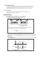
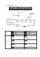
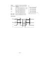

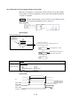
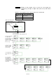
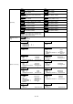
Table Of Contents
- Coverpage
- Safety Instructions
- Revision History
- Contents
- Introduction
- 1 Outline
- 2 Explanation of Functions
- 3 Q-PLC Multi-CPU
- 4 Q Motion CPU
- 5 SFC Program
- 6 SV22 Servo Programs
- 6.1 Servo program
- 6.1.1 Servo program configuration
- 6.1.2 List of servo commands
- 6.1.3 Linear control
- 6.1.4 Circular interpolation control using auxiliary point designation
- 6.1.5 Circular interpolation control using radius designation
- 6.1.6 Circular interpolation control using center point designation
- 6.1.7 Fixed-dimension feed control
- 6.1.8 Speed control
- 6.1.9 Speed/position changeover control
- 6.1.10 Speed changeover control
- 6.1.11 Constant-speed control
- 6.1.12 Repeated control (for speed changeover control and uniform speed control)
- 6.1.13 Simultaneous start
- 6.1.14 Zero point return
- 6.1.15 Position follow-up control
- 6.1.16 High-speed oscillation control
- 6.1.17 Helical interpolation control with auxiliary point designated
- 6.1.18 Helical interpolation control with radius designated
- 6.1.19 Helical interpolation control with center point designated
- 6.1.20 Current value change
- 6.1 Servo program
- 7 Operation Control Program
- 8 Windows Personal Computer Operations
- 9 Basic Practice Using the SV22 Real Mode
- 10 Applied Practice with SV22 Real Mode
- 10.1 Details of practice
- 10.2 Q172CPU practice machine system configuration
- 10.3 Practice SFC programs
- 10.4 Writing to the motion CPU
- 10.5 Program for operation
- 10.5.1 JOG operation
- 10.5.2 Main routine SFC program (real mode operation)
- 10.5.3 Execution of servo program (motion control step)
- 10.5.4 Stopping
- 10.5.5 Error reset
- 10.5.6 Current value change
- 10.5.7 Speed change (CHGV)
- 10.5.8 Reading actual current value
- 10.5.9 Continuous positioning
- 10.5.10 M code function
- 10.5.11 Indirect setting of servo program address
- 10.6 Operating the practice machine
- 11 Practicing with the SV22 Virtual Mode
- 11.1 Mechanism program
- 11.2 Details of practice
- 11.3 Starting up SW3RN-CAMP and creating the cam
- 11.4 SFC program for virtual mode
- 11.5 Editing the mechanism
- 11.6 Writing to the motion CPU
- 11.7 Reading of sequence program from Q-PLC CPU
- 11.8 SFC program for practice
- 11.9 Practice machine operations
- 11.10 Exercise (Roller setting)
- Appendix

10 - 20
10.5.3 Execution of servo program (motion control step)
When the servo program is executed at the motion control step of the SFC program,
the operation is executed according to the contents of the data and parameter block for
executed servo program.
Example 1 Example of SFC program used to execute the servo program No.10 (to
execute the linear interpolation of axis 1 and axis 2)
[Servo program]
Program No.: Mode ..............................
Axis linear interpolation command..............
Axis 1 address.........................................................
Axis 2 address.........................................................
Positioning speed ....................................................
AXIS
AXIS
COMPOSITE VELOCITY
DWELL
Real
[SFC program]
Servo program No. 10 start
SFC program No. 20
SFC program
No. 0
Real mode main
[Real mode main] program
The "Waiting point
positioning" is started
when X0 switch is turned
ON, and M2001 and
M2002 are turned OFF.
Waiting position
Waiting point positioning
Shift to END after completion of
motion control step for K10
G200
[Transition]
NOP
K10: REAL
[Motion control step]
1 ABS-2
AXIS 1, 0.0 µm
AXIS 2, 0.0 µm
COMPOSITE VELOCITY 4000.00 mm/min
DWELL 100 msec
PX0 : Positioning start command
[Timing chart]
M2401, M2421
Completion of positioning
M2400, M2420
Completion of positioning start
M2001, M2002
X0
Turned OFF when the
positioning is started or
when JOG operation is
started.