
Specifications
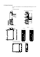
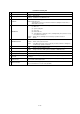
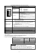

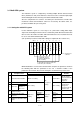
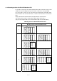
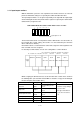
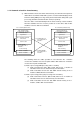
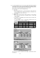
Table Of Contents
- Coverpage
- Safety Instructions
- Revision History
- Contents
- Introduction
- 1 Outline
- 2 Explanation of Functions
- 3 Q-PLC Multi-CPU
- 4 Q Motion CPU
- 5 SFC Program
- 6 SV22 Servo Programs
- 6.1 Servo program
- 6.1.1 Servo program configuration
- 6.1.2 List of servo commands
- 6.1.3 Linear control
- 6.1.4 Circular interpolation control using auxiliary point designation
- 6.1.5 Circular interpolation control using radius designation
- 6.1.6 Circular interpolation control using center point designation
- 6.1.7 Fixed-dimension feed control
- 6.1.8 Speed control
- 6.1.9 Speed/position changeover control
- 6.1.10 Speed changeover control
- 6.1.11 Constant-speed control
- 6.1.12 Repeated control (for speed changeover control and uniform speed control)
- 6.1.13 Simultaneous start
- 6.1.14 Zero point return
- 6.1.15 Position follow-up control
- 6.1.16 High-speed oscillation control
- 6.1.17 Helical interpolation control with auxiliary point designated
- 6.1.18 Helical interpolation control with radius designated
- 6.1.19 Helical interpolation control with center point designated
- 6.1.20 Current value change
- 6.1 Servo program
- 7 Operation Control Program
- 8 Windows Personal Computer Operations
- 9 Basic Practice Using the SV22 Real Mode
- 10 Applied Practice with SV22 Real Mode
- 10.1 Details of practice
- 10.2 Q172CPU practice machine system configuration
- 10.3 Practice SFC programs
- 10.4 Writing to the motion CPU
- 10.5 Program for operation
- 10.5.1 JOG operation
- 10.5.2 Main routine SFC program (real mode operation)
- 10.5.3 Execution of servo program (motion control step)
- 10.5.4 Stopping
- 10.5.5 Error reset
- 10.5.6 Current value change
- 10.5.7 Speed change (CHGV)
- 10.5.8 Reading actual current value
- 10.5.9 Continuous positioning
- 10.5.10 M code function
- 10.5.11 Indirect setting of servo program address
- 10.6 Operating the practice machine
- 11 Practicing with the SV22 Virtual Mode
- 11.1 Mechanism program
- 11.2 Details of practice
- 11.3 Starting up SW3RN-CAMP and creating the cam
- 11.4 SFC program for virtual mode
- 11.5 Editing the mechanism
- 11.6 Writing to the motion CPU
- 11.7 Reading of sequence program from Q-PLC CPU
- 11.8 SFC program for practice
- 11.9 Practice machine operations
- 11.10 Exercise (Roller setting)
- Appendix
2 - 7
Q173CPU(N)/Q172CPU(N) switch and connector functions
No. Item Function
DIP switches 1 Use prohibited (OFF at shipment from maker)
DIP switches 2
DIP switches 3
ROM operation setting (OFF at shipment from maker)
SW3 SW2
OFF OFF → RAM operation mode
OFF ON → Setting prohibited
ON OFF → Setting prohibited
ON ON → ROM operation mode
DIP switches 4 Use prohibited (OFF at shipment from maker)
13)
DIP switch
1
2
3
4
5
ON SW
DIP switches 5
Install/ROM write switches
ON : Install/ROM write mode
OFF : Normal mode (RAM operation mode/ROM operation mode)
This switch is turned ON in the following cases:
• When installing the CPU module operating system (OS) from a
peripheral device.
• When writing the programs and parameters stored in the RAM into
the ROM for ROM operation.
To change the mode, change the switch setting and then restart the
system.
14)
RUN/STOP
(momentary switch)
• Use this switch by setting it to RUN or STOP.
RUN : The motion program is executed.
STOP : The motion program is stopped.
15)
RESET/L.CLR switch*
1
(momentary switch)
• RESET : The hardware is reset when the switch is set to the RESET side once.
When an operation error occurs, the error is reset, and the operation is initialized.
• L.CLR : All data in the latch area, set with the parameters, is cleared (set to OFF or 0).
(Data other than that in the latch area is cleared simultaneously.)
Latch clear operation methods
(1) Set the RUN/STOP switch to STOP.
(2) Set the RESET/L.CLR switch to the L.CLR side several times until the MOTION RUN LED
flickers.
(MOTION RUN LED flicker: Preparation for latch clear completed.)
(3) Set the RESET/L.CLR switch to the L.CLR side again. (MOTION RUN LED turns OFF.)
16) Module fixing screw hole
• Screw hole used to fix module onto base unit. (M3×12 screw: prepared by user)
17) Module fixing projection
• Projection used to fix module to base unit.
18) CN2 connector
• Connector for establishing SSCNET connection with personal computer.
19) CN1 connector*
2
• Connector for connecting with MR-H-BN/MR-J2S-B/MR-J2-B/MR-J2M-B/MR-J2-03B5.
20) Cooling fan connector*
3
• Connector for connecting Q172CPU/Q173CPU dedicated cooling fan unit (Q170FAN).
21) Cooling fan unit*
4
• Q172CPU/Q173CPU dedicated cooling fan unit (Q170FAN)
*1: With the multi-CPU system, the QCPU/motion CPU for units No. 2 to No. 4 cannot be reset independently. When reset, MULTI CPU
DOWN (error code: 7000) will occur in the other machines, and the entire multi-CPU system will stop. To reset the entire system, reset
the No. 1 unit's QCPU.
*2: When using the Q173, the signals for the SSCNET1 to 4 systems are input in the CN1 connector. These must be branched to each
system using a line divider Q173DV or a branch cable (A173J2B∆CBLoM/Q173HB∆CBLoM).
*3: Do not remove the caution plate until the cooling fan unit (Q170FAN) is used.
*4: Conditions for using cooling fan unit (Q170FAN):
Controller peripheral temperature
Number of Q motion CPUs in use
40°C or less
40°C or more,
55°C or less
One Q172CPU/Q173CPU module
Cooling fan not
required
Cooling fan required
Two or more Q172CPU/Q173CPU modules Cooling fan required
Q172CPUN/Q173CPUN Cooling fan not required
Point
1) Turn the power OFF before setting the install switch.
2) After setting the switch, turn the power ON and check the switch state.
3) In the default state, the switch is set as shown above. (n) indicates the setting.
4) After setting the switch. Turn the power ON and check the switch state.