
Specifications
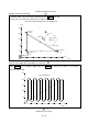

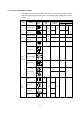
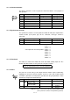
Table Of Contents
- Coverpage
- Safety Instructions
- Revision History
- Contents
- Introduction
- 1 Outline
- 2 Explanation of Functions
- 3 Q-PLC Multi-CPU
- 4 Q Motion CPU
- 5 SFC Program
- 6 SV22 Servo Programs
- 6.1 Servo program
- 6.1.1 Servo program configuration
- 6.1.2 List of servo commands
- 6.1.3 Linear control
- 6.1.4 Circular interpolation control using auxiliary point designation
- 6.1.5 Circular interpolation control using radius designation
- 6.1.6 Circular interpolation control using center point designation
- 6.1.7 Fixed-dimension feed control
- 6.1.8 Speed control
- 6.1.9 Speed/position changeover control
- 6.1.10 Speed changeover control
- 6.1.11 Constant-speed control
- 6.1.12 Repeated control (for speed changeover control and uniform speed control)
- 6.1.13 Simultaneous start
- 6.1.14 Zero point return
- 6.1.15 Position follow-up control
- 6.1.16 High-speed oscillation control
- 6.1.17 Helical interpolation control with auxiliary point designated
- 6.1.18 Helical interpolation control with radius designated
- 6.1.19 Helical interpolation control with center point designated
- 6.1.20 Current value change
- 6.1 Servo program
- 7 Operation Control Program
- 8 Windows Personal Computer Operations
- 9 Basic Practice Using the SV22 Real Mode
- 10 Applied Practice with SV22 Real Mode
- 10.1 Details of practice
- 10.2 Q172CPU practice machine system configuration
- 10.3 Practice SFC programs
- 10.4 Writing to the motion CPU
- 10.5 Program for operation
- 10.5.1 JOG operation
- 10.5.2 Main routine SFC program (real mode operation)
- 10.5.3 Execution of servo program (motion control step)
- 10.5.4 Stopping
- 10.5.5 Error reset
- 10.5.6 Current value change
- 10.5.7 Speed change (CHGV)
- 10.5.8 Reading actual current value
- 10.5.9 Continuous positioning
- 10.5.10 M code function
- 10.5.11 Indirect setting of servo program address
- 10.6 Operating the practice machine
- 11 Practicing with the SV22 Virtual Mode
- 11.1 Mechanism program
- 11.2 Details of practice
- 11.3 Starting up SW3RN-CAMP and creating the cam
- 11.4 SFC program for virtual mode
- 11.5 Editing the mechanism
- 11.6 Writing to the motion CPU
- 11.7 Reading of sequence program from Q-PLC CPU
- 11.8 SFC program for practice
- 11.9 Practice machine operations
- 11.10 Exercise (Roller setting)
- Appendix
10 - 44
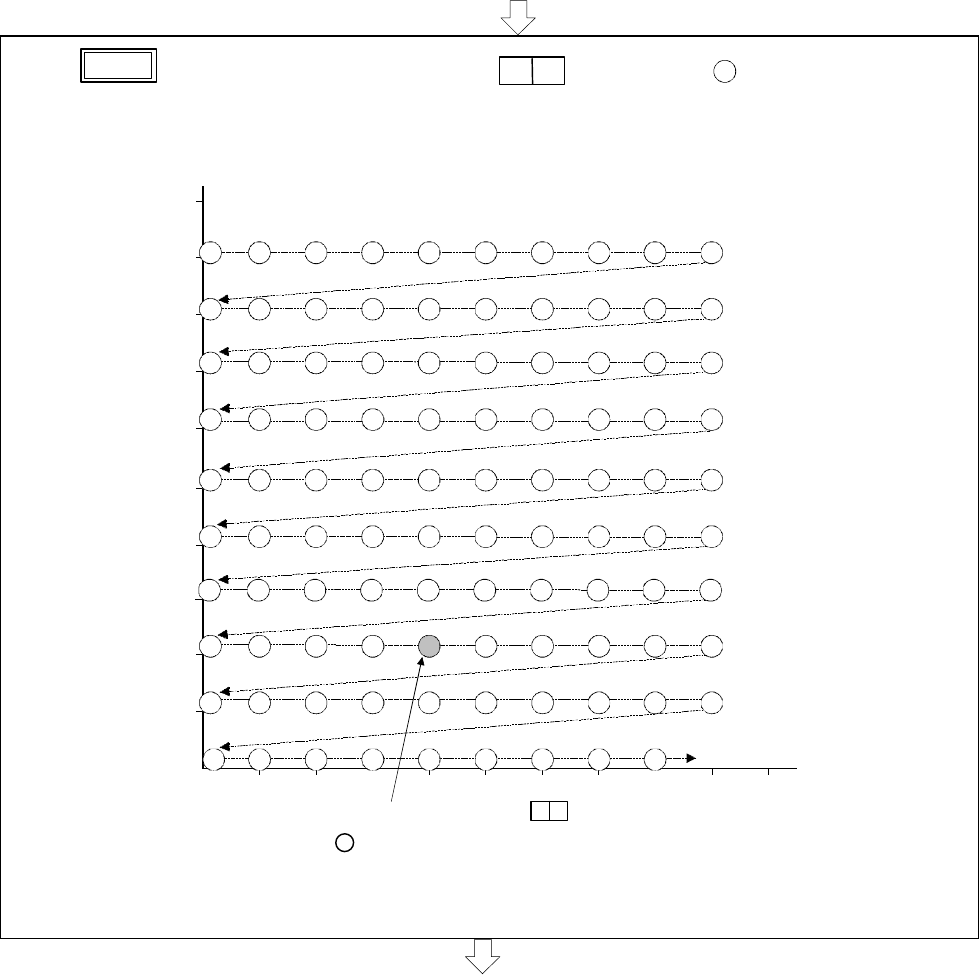
[Indirect setting of positioning address]
(Continued from previous page)
• If
X7
is pressed with the digital switch set to
7 5
, the address of '
75
' is stored in the D4006,
D4007, D4008 and D4009 for positioning when the servo program No.25 is executed.
The positioning control is executed in succession to the position in which the address is changed to
'(76), ...' and then to the 'END' position.
10 20 30 40 50 60 70 80 90 100
92
93
94
95
96
97
98
99
82 83 84 85 86 87 88 89 90
72
73
74
75
76
77
78
79
80
32 33 34 35 36 37 38 39 40
81
71
31
21
91
22
23
24
25
26
27
28
29
30
20
40
0
120
140
160
END
42 43 44 45 46 47 48 49 50 41
52
53
54
55
56
57
58
59
60
51
62 63 64 65 66 67 68 69 70 61
180
200
12 13 14 15 16 17 18 19 20 11
1
2
3
4
5
6
7
8
9
10
100
80
60
(mm)
When the digital switch is set to , the axis is positioned to this position.
The positioning operation is executed in succession thereafter from this position
' 76 ' to 'END'.
7 5
The circled No. indicates the designated position No.
(Continued on next page)