
Specifications

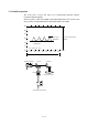
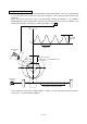

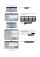
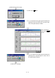
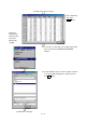
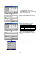
Table Of Contents
- Coverpage
- Safety Instructions
- Revision History
- Contents
- Introduction
- 1 Outline
- 2 Explanation of Functions
- 3 Q-PLC Multi-CPU
- 4 Q Motion CPU
- 5 SFC Program
- 6 SV22 Servo Programs
- 6.1 Servo program
- 6.1.1 Servo program configuration
- 6.1.2 List of servo commands
- 6.1.3 Linear control
- 6.1.4 Circular interpolation control using auxiliary point designation
- 6.1.5 Circular interpolation control using radius designation
- 6.1.6 Circular interpolation control using center point designation
- 6.1.7 Fixed-dimension feed control
- 6.1.8 Speed control
- 6.1.9 Speed/position changeover control
- 6.1.10 Speed changeover control
- 6.1.11 Constant-speed control
- 6.1.12 Repeated control (for speed changeover control and uniform speed control)
- 6.1.13 Simultaneous start
- 6.1.14 Zero point return
- 6.1.15 Position follow-up control
- 6.1.16 High-speed oscillation control
- 6.1.17 Helical interpolation control with auxiliary point designated
- 6.1.18 Helical interpolation control with radius designated
- 6.1.19 Helical interpolation control with center point designated
- 6.1.20 Current value change
- 6.1 Servo program
- 7 Operation Control Program
- 8 Windows Personal Computer Operations
- 9 Basic Practice Using the SV22 Real Mode
- 10 Applied Practice with SV22 Real Mode
- 10.1 Details of practice
- 10.2 Q172CPU practice machine system configuration
- 10.3 Practice SFC programs
- 10.4 Writing to the motion CPU
- 10.5 Program for operation
- 10.5.1 JOG operation
- 10.5.2 Main routine SFC program (real mode operation)
- 10.5.3 Execution of servo program (motion control step)
- 10.5.4 Stopping
- 10.5.5 Error reset
- 10.5.6 Current value change
- 10.5.7 Speed change (CHGV)
- 10.5.8 Reading actual current value
- 10.5.9 Continuous positioning
- 10.5.10 M code function
- 10.5.11 Indirect setting of servo program address
- 10.6 Operating the practice machine
- 11 Practicing with the SV22 Virtual Mode
- 11.1 Mechanism program
- 11.2 Details of practice
- 11.3 Starting up SW3RN-CAMP and creating the cam
- 11.4 SFC program for virtual mode
- 11.5 Editing the mechanism
- 11.6 Writing to the motion CPU
- 11.7 Reading of sequence program from Q-PLC CPU
- 11.8 SFC program for practice
- 11.9 Practice machine operations
- 11.10 Exercise (Roller setting)
- Appendix
11 - 15
(Continued from previous page)
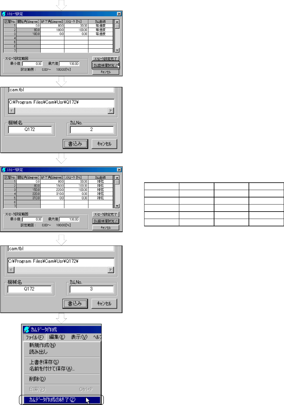
16) Create the cam data for cam No.2 with the same
procedure as for cam No.1.
For cam No.2, change the "Cam curve selection" of
cam No.1, to 'Uniform speed'.
(The other items are the same as cam No.1.)
Select [Edit] and then [Cam curve selection], and set
the full-stroke to 'Uniform speed'.
17) When saving the data with 'Save as', set the "Cam
No." to '2'.
18) Set the cam No.3 with the same procedure.
Set the "Stroke setting" as shown below.
Area No. Start angle End angle Stroke
1 0.0 80.0 30.00
2 150.0 100.00
3 220.0 100.00
4 310.0 0.00
50.00.00
Stroke setting range "Minimum value": 0.00, "Maximum value": 100.00
Set the "Stroke setting range" to 'Double circle'.
19) When saving the data with 'Save as', set the "Cam
No." to '3'.
20) Click on [File], and then the [Cam data creation
completed] menu.
This completes creation of the cam data.