
Specifications
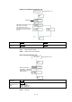
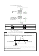
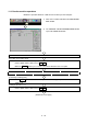
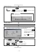
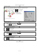
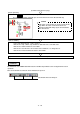
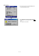
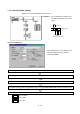

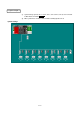
Table Of Contents
- Coverpage
- Safety Instructions
- Revision History
- Contents
- Introduction
- 1 Outline
- 2 Explanation of Functions
- 3 Q-PLC Multi-CPU
- 4 Q Motion CPU
- 5 SFC Program
- 6 SV22 Servo Programs
- 6.1 Servo program
- 6.1.1 Servo program configuration
- 6.1.2 List of servo commands
- 6.1.3 Linear control
- 6.1.4 Circular interpolation control using auxiliary point designation
- 6.1.5 Circular interpolation control using radius designation
- 6.1.6 Circular interpolation control using center point designation
- 6.1.7 Fixed-dimension feed control
- 6.1.8 Speed control
- 6.1.9 Speed/position changeover control
- 6.1.10 Speed changeover control
- 6.1.11 Constant-speed control
- 6.1.12 Repeated control (for speed changeover control and uniform speed control)
- 6.1.13 Simultaneous start
- 6.1.14 Zero point return
- 6.1.15 Position follow-up control
- 6.1.16 High-speed oscillation control
- 6.1.17 Helical interpolation control with auxiliary point designated
- 6.1.18 Helical interpolation control with radius designated
- 6.1.19 Helical interpolation control with center point designated
- 6.1.20 Current value change
- 6.1 Servo program
- 7 Operation Control Program
- 8 Windows Personal Computer Operations
- 9 Basic Practice Using the SV22 Real Mode
- 10 Applied Practice with SV22 Real Mode
- 10.1 Details of practice
- 10.2 Q172CPU practice machine system configuration
- 10.3 Practice SFC programs
- 10.4 Writing to the motion CPU
- 10.5 Program for operation
- 10.5.1 JOG operation
- 10.5.2 Main routine SFC program (real mode operation)
- 10.5.3 Execution of servo program (motion control step)
- 10.5.4 Stopping
- 10.5.5 Error reset
- 10.5.6 Current value change
- 10.5.7 Speed change (CHGV)
- 10.5.8 Reading actual current value
- 10.5.9 Continuous positioning
- 10.5.10 M code function
- 10.5.11 Indirect setting of servo program address
- 10.6 Operating the practice machine
- 11 Practicing with the SV22 Virtual Mode
- 11.1 Mechanism program
- 11.2 Details of practice
- 11.3 Starting up SW3RN-CAMP and creating the cam
- 11.4 SFC program for virtual mode
- 11.5 Editing the mechanism
- 11.6 Writing to the motion CPU
- 11.7 Reading of sequence program from Q-PLC CPU
- 11.8 SFC program for practice
- 11.9 Practice machine operations
- 11.10 Exercise (Roller setting)
- Appendix
11 - 40
[Changing to virtual mode]
(Continued from previous page)
Set the mode selector switch from [REAL] (X19 ON) to [VIRTUAL] (X1A ON).
The virtual mode is entered if the
X0A
lamp is on.
If the
X0A
lamp does not turn on, and the
X0C
error lamp flickers, check the
details of the error, and correct the settings.
Confirming the error
[Error list] → [Error list] menu
↓
[Virtual drive servomotor axis 1
current value monitor]
Enlarge the current value monitor in the MONITOR window.
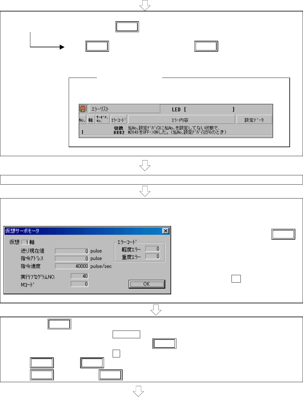
[Mechanism monitor]
• Change the window to the MECHANISM EDIT window (active window).
• Click on [Mode change] and then the [Monitor] menu in the MECHANISM EDIT window.
• Double-click on the virtual servomotor to display the DETAILS MONITOR.
If the current value change
X0A
for virtual axis 1 is pressed when the
"Current feed value" is not '0', the
value will be set to '0'.
Click on the OK button to close the
window.
[Starting in the virtual mode (cam No. 1)]
• When
X1 is pressed, the cam curve will be drawn.
([FEED PRE. VAL.] will stop at 5242880 pulse.)
• The axis will return to the standby point when
X0 is pressed.
([FEED PRE. VAL.] will stop at 0 pulse.)
•
X0D stop and
X0E sudden stop are valid during this operation.
•
X05 forward jog and
X03 reverse jog are valid when stopped.
(Continued on next page)