
Specifications
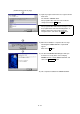
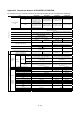
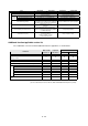
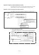
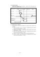
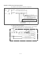
Table Of Contents
- Coverpage
- Safety Instructions
- Revision History
- Contents
- Introduction
- 1 Outline
- 2 Explanation of Functions
- 3 Q-PLC Multi-CPU
- 4 Q Motion CPU
- 5 SFC Program
- 6 SV22 Servo Programs
- 6.1 Servo program
- 6.1.1 Servo program configuration
- 6.1.2 List of servo commands
- 6.1.3 Linear control
- 6.1.4 Circular interpolation control using auxiliary point designation
- 6.1.5 Circular interpolation control using radius designation
- 6.1.6 Circular interpolation control using center point designation
- 6.1.7 Fixed-dimension feed control
- 6.1.8 Speed control
- 6.1.9 Speed/position changeover control
- 6.1.10 Speed changeover control
- 6.1.11 Constant-speed control
- 6.1.12 Repeated control (for speed changeover control and uniform speed control)
- 6.1.13 Simultaneous start
- 6.1.14 Zero point return
- 6.1.15 Position follow-up control
- 6.1.16 High-speed oscillation control
- 6.1.17 Helical interpolation control with auxiliary point designated
- 6.1.18 Helical interpolation control with radius designated
- 6.1.19 Helical interpolation control with center point designated
- 6.1.20 Current value change
- 6.1 Servo program
- 7 Operation Control Program
- 8 Windows Personal Computer Operations
- 9 Basic Practice Using the SV22 Real Mode
- 10 Applied Practice with SV22 Real Mode
- 10.1 Details of practice
- 10.2 Q172CPU practice machine system configuration
- 10.3 Practice SFC programs
- 10.4 Writing to the motion CPU
- 10.5 Program for operation
- 10.5.1 JOG operation
- 10.5.2 Main routine SFC program (real mode operation)
- 10.5.3 Execution of servo program (motion control step)
- 10.5.4 Stopping
- 10.5.5 Error reset
- 10.5.6 Current value change
- 10.5.7 Speed change (CHGV)
- 10.5.8 Reading actual current value
- 10.5.9 Continuous positioning
- 10.5.10 M code function
- 10.5.11 Indirect setting of servo program address
- 10.6 Operating the practice machine
- 11 Practicing with the SV22 Virtual Mode
- 11.1 Mechanism program
- 11.2 Details of practice
- 11.3 Starting up SW3RN-CAMP and creating the cam
- 11.4 SFC program for virtual mode
- 11.5 Editing the mechanism
- 11.6 Writing to the motion CPU
- 11.7 Reading of sequence program from Q-PLC CPU
- 11.8 SFC program for practice
- 11.9 Practice machine operations
- 11.10 Exercise (Roller setting)
- Appendix
A - 32
Appendix 5.2 CHGA current value change command
This command is used to change the current value of a stopped axis.
Command
SP.CHGA (n1) (S1) (S2) (D1) (D2)
Command
S.CHGA (n1) (S1) (S2) (D1) (D2)
[Comman
symbol]
SP.CHG
S.CHG
[Execution
condition]
Completion device
(D1+0): Device to turn on one-scan after completion of
command start accept
(D1+1): Device to turn on one-scan after abnormal
completion of command start accept (In this
case, (D1+0) is turned on at the same time.)
Device to store completion status
Setting of current value to be changed
Head input/output No.
÷
16 of object
machine CPU
No. 2 machine: 3E1H
No. 3 machine: 3E2H
No. 4 machine: 3E3H
Axis No. ('Jn' = J1 to J8) of which current value is changed
Encoder axis No. ('En' = E1 to E8) of which current value is changed
Cam axis No. ('Cn' = C1 to C8) of which current value per rotation is changed
(1) CHGA command program example
This program is used to change the current value of axis No. 1 (No. 2 machine
motion CPU) from that of axis No. 1 (No. 1 machine PLC CPU) to "10".
H3E1 "J1" K10 M0 D0
RST
M100
SP.CHGA
Current value after change
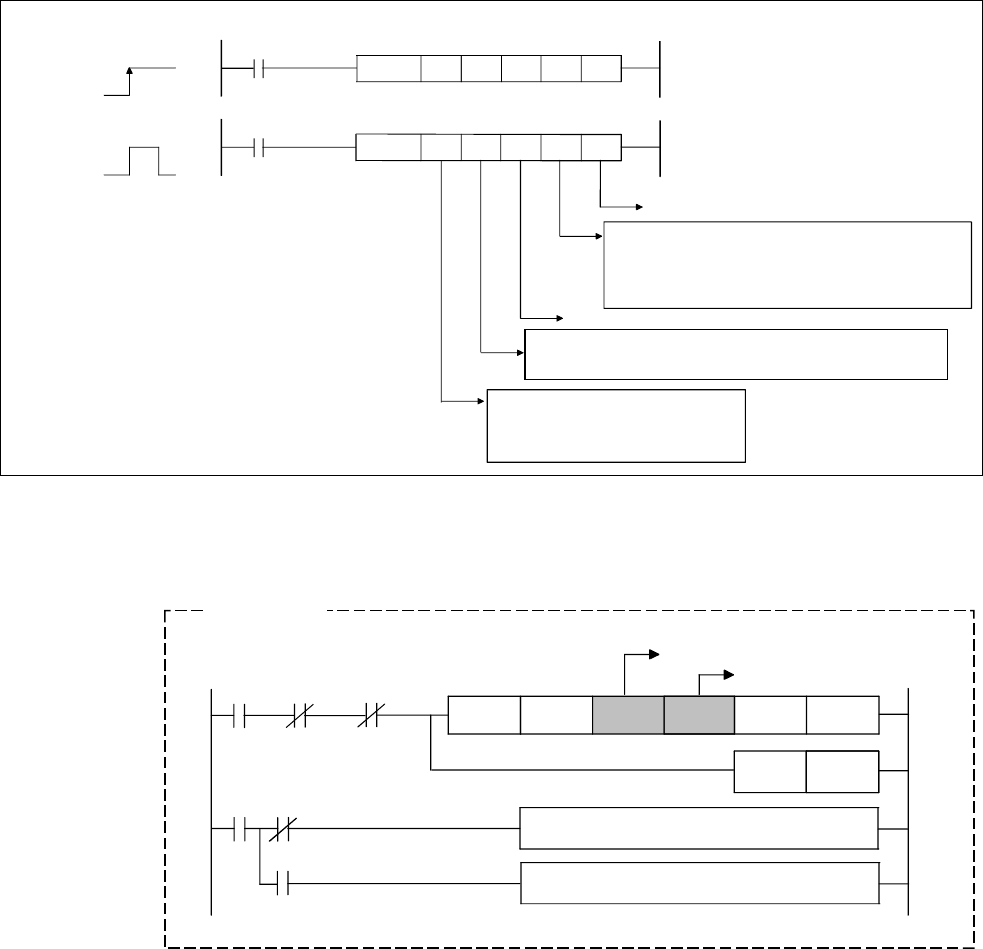
M0
M1
M1
M100
U3E1
¥G48.0
U3E1
¥G516.0
Designation of object axis
Normally completed program
Abnormally completed program
CPU1
→
Local
CPU interrupt
accept fla
Number 2
machine axis 1
start accept fla
Example
No. 2