
Specifications

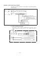
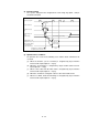
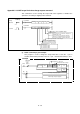

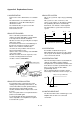
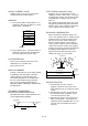
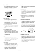
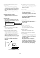
Table Of Contents
- Coverpage
- Safety Instructions
- Revision History
- Contents
- Introduction
- 1 Outline
- 2 Explanation of Functions
- 3 Q-PLC Multi-CPU
- 4 Q Motion CPU
- 5 SFC Program
- 6 SV22 Servo Programs
- 6.1 Servo program
- 6.1.1 Servo program configuration
- 6.1.2 List of servo commands
- 6.1.3 Linear control
- 6.1.4 Circular interpolation control using auxiliary point designation
- 6.1.5 Circular interpolation control using radius designation
- 6.1.6 Circular interpolation control using center point designation
- 6.1.7 Fixed-dimension feed control
- 6.1.8 Speed control
- 6.1.9 Speed/position changeover control
- 6.1.10 Speed changeover control
- 6.1.11 Constant-speed control
- 6.1.12 Repeated control (for speed changeover control and uniform speed control)
- 6.1.13 Simultaneous start
- 6.1.14 Zero point return
- 6.1.15 Position follow-up control
- 6.1.16 High-speed oscillation control
- 6.1.17 Helical interpolation control with auxiliary point designated
- 6.1.18 Helical interpolation control with radius designated
- 6.1.19 Helical interpolation control with center point designated
- 6.1.20 Current value change
- 6.1 Servo program
- 7 Operation Control Program
- 8 Windows Personal Computer Operations
- 9 Basic Practice Using the SV22 Real Mode
- 10 Applied Practice with SV22 Real Mode
- 10.1 Details of practice
- 10.2 Q172CPU practice machine system configuration
- 10.3 Practice SFC programs
- 10.4 Writing to the motion CPU
- 10.5 Program for operation
- 10.5.1 JOG operation
- 10.5.2 Main routine SFC program (real mode operation)
- 10.5.3 Execution of servo program (motion control step)
- 10.5.4 Stopping
- 10.5.5 Error reset
- 10.5.6 Current value change
- 10.5.7 Speed change (CHGV)
- 10.5.8 Reading actual current value
- 10.5.9 Continuous positioning
- 10.5.10 M code function
- 10.5.11 Indirect setting of servo program address
- 10.6 Operating the practice machine
- 11 Practicing with the SV22 Virtual Mode
- 11.1 Mechanism program
- 11.2 Details of practice
- 11.3 Starting up SW3RN-CAMP and creating the cam
- 11.4 SFC program for virtual mode
- 11.5 Editing the mechanism
- 11.6 Writing to the motion CPU
- 11.7 Reading of sequence program from Q-PLC CPU
- 11.8 SFC program for practice
- 11.9 Practice machine operations
- 11.10 Exercise (Roller setting)
- Appendix
A - 36
Appendix 5.4 CHGT torque limit value change request command
This command is used to change the torque limit value regardless of whether the
operation is executing or stopping in the real mode.
Command
SP.CHGT (n1) (S1) (S2) (D1) (D2)
Command
S.CHGT (n1) (S1) (S2) (D1) (D2)
[Comman
symbol]
SP.CHG
S.CHG
[Execution
condition]
Completion device
(D1+0): Device to turn on one-scan after completion of
command start accept
(D1+1): Device to turn on one-scan after abnormal
completion of command start accept (In this
case, (D1+0) is turned on at the same time.)
Device to store completion status
Setting of torque limit value to be changed
Axis No. ('Jn') of which torque
limit value is changed J1 to J8
Head input/output No.
÷
16 of object
machine CPU
No. 2 machine: 3E1H
No. 3 machine: 3E2H
No. 4 machine: 3E3H
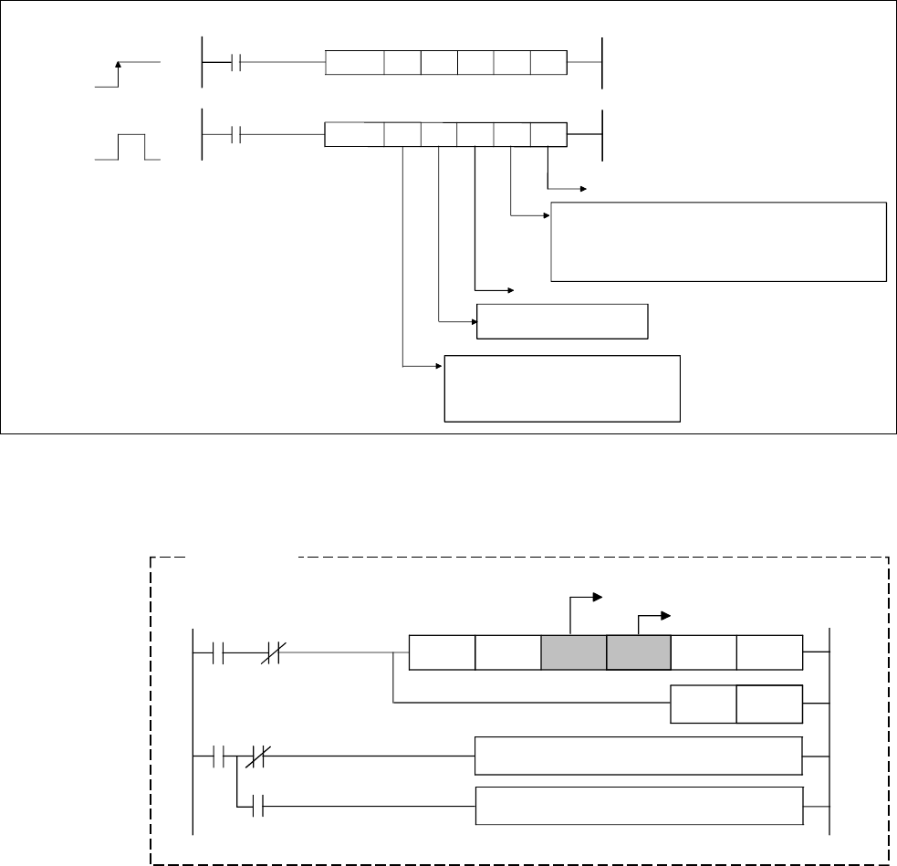
(1) CHGT command program example
This program is used to change the torque limit value of axis No. 1 (No. 2
machine motion CPU) from that of axis No. 1 (No. 1 machine PLC CPU) to "10%".
H3E1 "J1"
K10
M0 D0
RST
M100
SP.CHGT
M0
M1
M1
M100
U3E1
¥G48.0
Current value after change
Designation of object axis
Normally completed program
Abnormally completed program
CPU1
→
Local
CPU interrupt
accept fla
Example