
Specifications
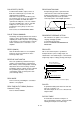
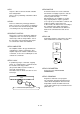
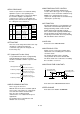
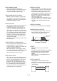

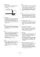
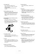
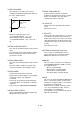
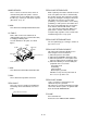

Table Of Contents
- Coverpage
- Safety Instructions
- Revision History
- Contents
- Introduction
- 1 Outline
- 2 Explanation of Functions
- 3 Q-PLC Multi-CPU
- 4 Q Motion CPU
- 5 SFC Program
- 6 SV22 Servo Programs
- 6.1 Servo program
- 6.1.1 Servo program configuration
- 6.1.2 List of servo commands
- 6.1.3 Linear control
- 6.1.4 Circular interpolation control using auxiliary point designation
- 6.1.5 Circular interpolation control using radius designation
- 6.1.6 Circular interpolation control using center point designation
- 6.1.7 Fixed-dimension feed control
- 6.1.8 Speed control
- 6.1.9 Speed/position changeover control
- 6.1.10 Speed changeover control
- 6.1.11 Constant-speed control
- 6.1.12 Repeated control (for speed changeover control and uniform speed control)
- 6.1.13 Simultaneous start
- 6.1.14 Zero point return
- 6.1.15 Position follow-up control
- 6.1.16 High-speed oscillation control
- 6.1.17 Helical interpolation control with auxiliary point designated
- 6.1.18 Helical interpolation control with radius designated
- 6.1.19 Helical interpolation control with center point designated
- 6.1.20 Current value change
- 6.1 Servo program
- 7 Operation Control Program
- 8 Windows Personal Computer Operations
- 9 Basic Practice Using the SV22 Real Mode
- 10 Applied Practice with SV22 Real Mode
- 10.1 Details of practice
- 10.2 Q172CPU practice machine system configuration
- 10.3 Practice SFC programs
- 10.4 Writing to the motion CPU
- 10.5 Program for operation
- 10.5.1 JOG operation
- 10.5.2 Main routine SFC program (real mode operation)
- 10.5.3 Execution of servo program (motion control step)
- 10.5.4 Stopping
- 10.5.5 Error reset
- 10.5.6 Current value change
- 10.5.7 Speed change (CHGV)
- 10.5.8 Reading actual current value
- 10.5.9 Continuous positioning
- 10.5.10 M code function
- 10.5.11 Indirect setting of servo program address
- 10.6 Operating the practice machine
- 11 Practicing with the SV22 Virtual Mode
- 11.1 Mechanism program
- 11.2 Details of practice
- 11.3 Starting up SW3RN-CAMP and creating the cam
- 11.4 SFC program for virtual mode
- 11.5 Editing the mechanism
- 11.6 Writing to the motion CPU
- 11.7 Reading of sequence program from Q-PLC CPU
- 11.8 SFC program for practice
- 11.9 Practice machine operations
- 11.10 Exercise (Roller setting)
- Appendix

A - 55
SERVO RESPONSE
Set the responsiveness for automatic tuning.
Optimum response corresponding to the
machine's rigidity can be selected. The higher
the machine's rigidity is, the higher the
responsiveness can be set. This allows the
tracking of the command to be improved, and
the settling time to be shortened.
Details
Machine
type
Setting
value
Responsive-ness
Guideline to
applicable
machine's rigidity
Load
inertia
target
GD
L
2
/GD
M
2
Position
settling time
guideline =
GD
L
2
/GD
M
2
within 5-fold
5 to 300ms
1 to 70msNormal
1
2
3
4
5
Low response
Medium response
High response
Low rigidity
to
Medium rigidity
to
High rigidity
1 to 30ms
70 to 400ms
10 to 100ms
Large
friction
8
9
A
B
C
Low response
Medium response
High response
Low rigidity
to
Medium rigidity
to
High rigidity
1 to 10-fold
10 to 50ms
SETTING TIME
This refers to the delay time from the time stop
command is completed to when the
servomotor stops (time for droop pulse to
increment by one).
SFC (Sequential Function Chart)
A sequential function chart is a programming
method optimally structured for running a
machine's automatic control in sequence with
the PLC.
Start preparation
Start preparations OK
Execution of advance
operation servo program
Positioning complete
Execution of extrusion
operation servo program
Execution of retract
operation servo program
Positioning complete
Positioning complete
SIMPLE HARMONIC MOTION
This is a type of cam curve.
With this movement, the acceleration pattern
moves in the same manner as a right angle
axis element in uniform circular motion.
This curve has smooth and good
characteristics so is suitable for low-speed
applications.
Acceleration can be noncontinuous and
vibration can occur easily.
SIMULTANEOUS START CONTROL
A START command that simultaneously
executes two to three types of servo programs,
and starts several servomotors simultaneously.
Multiple axes designated in the special
registers for JOG operation are simultaneously
started by the special relay.
SKIP FUNCTION
Function that allows the next positioning to be
started if the external STOP signal turns ON
during positioning control or if the external
STOP signal remains ON while stopped.
If the external STOP signal input invalid flag is
turned ON during deceleration and the start
accept flag is turned OFF, the next positioning
will start with the SVST command.
SLAVE AXIS
Refer to the term "MASTER AXIS".
SMOOTHING CLUTCH
Clutch used as a conveyance module in the
virtual mode. The smoothing time constant is
set for this clutch.
The rotation operation can be smoothly
conveyed when the clutch is ON and OFF.
The direct clutch refers to when the smoothing
time constant is set to zero.
SMOOTHING TIME CONSTANT t
V
A
B
A
t t
A
B
Acceleration with
smoothing process
Deceleration with
smoothing process
Refer to the term "SMOOTHING CLUTCH".
SPEED CHANGE
Refer to the term "DSFLP COMMAND".