
Specifications
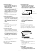
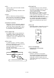
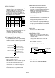
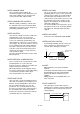

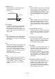
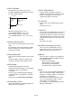
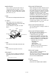

Table Of Contents
- Coverpage
- Safety Instructions
- Revision History
- Contents
- Introduction
- 1 Outline
- 2 Explanation of Functions
- 3 Q-PLC Multi-CPU
- 4 Q Motion CPU
- 5 SFC Program
- 6 SV22 Servo Programs
- 6.1 Servo program
- 6.1.1 Servo program configuration
- 6.1.2 List of servo commands
- 6.1.3 Linear control
- 6.1.4 Circular interpolation control using auxiliary point designation
- 6.1.5 Circular interpolation control using radius designation
- 6.1.6 Circular interpolation control using center point designation
- 6.1.7 Fixed-dimension feed control
- 6.1.8 Speed control
- 6.1.9 Speed/position changeover control
- 6.1.10 Speed changeover control
- 6.1.11 Constant-speed control
- 6.1.12 Repeated control (for speed changeover control and uniform speed control)
- 6.1.13 Simultaneous start
- 6.1.14 Zero point return
- 6.1.15 Position follow-up control
- 6.1.16 High-speed oscillation control
- 6.1.17 Helical interpolation control with auxiliary point designated
- 6.1.18 Helical interpolation control with radius designated
- 6.1.19 Helical interpolation control with center point designated
- 6.1.20 Current value change
- 6.1 Servo program
- 7 Operation Control Program
- 8 Windows Personal Computer Operations
- 9 Basic Practice Using the SV22 Real Mode
- 10 Applied Practice with SV22 Real Mode
- 10.1 Details of practice
- 10.2 Q172CPU practice machine system configuration
- 10.3 Practice SFC programs
- 10.4 Writing to the motion CPU
- 10.5 Program for operation
- 10.5.1 JOG operation
- 10.5.2 Main routine SFC program (real mode operation)
- 10.5.3 Execution of servo program (motion control step)
- 10.5.4 Stopping
- 10.5.5 Error reset
- 10.5.6 Current value change
- 10.5.7 Speed change (CHGV)
- 10.5.8 Reading actual current value
- 10.5.9 Continuous positioning
- 10.5.10 M code function
- 10.5.11 Indirect setting of servo program address
- 10.6 Operating the practice machine
- 11 Practicing with the SV22 Virtual Mode
- 11.1 Mechanism program
- 11.2 Details of practice
- 11.3 Starting up SW3RN-CAMP and creating the cam
- 11.4 SFC program for virtual mode
- 11.5 Editing the mechanism
- 11.6 Writing to the motion CPU
- 11.7 Reading of sequence program from Q-PLC CPU
- 11.8 SFC program for practice
- 11.9 Practice machine operations
- 11.10 Exercise (Roller setting)
- Appendix
A - 60
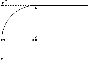
VICINITY PASSAGE
This allows the pass points to be moved
smoothly during 3D interpolation CP control of
the SV51 dedicated robot.
P2A3
P1
A1
P0
A2
Pass point
Vicinity amount
(radius)
Vicinity amount
(radius)
Center point
When the vicinity passage is zero:
The path will follow P0 → P1 → P2.
When vicinity passage is designated:
The path will follow P0 → A1 → A2 → A3 →
P2.
VIRTUAL AUXILIARY INPUT
One of the mechanism programs for the virtual
mode.
Incremental or decremental rotation is applied
from the auxiliary axis' virtual servomotor or
synchronous encoder.
VIRTUAL MAIN SHAFT
One of the mechanism programs for the virtual
mode.
The drive module's rotation is coupled to the
conveyance module's gears with this shaft.
VIRTUAL MODE
A method of operating the mechanism
program drive modules with the servo program
or external encoder, and driving the
servomotor.
Conversely, the method of directly driving the
servomotor with a servo program is called the
real mode.
Refer to the term "MECHANISM PROGRAM".
VIRTUAL MODE STATUS
Special relay M2044, a monitor that allows the
virtual mode to be confirmed.
VIRTUAL SERVOMOTOR
A drive module used in the mechanism
program for the virtual mode, which is started
by the servo program. The main shaft is
coupled to the virtual servomotor.
Vm VELOCITY
Refers to the cam's maximum dimensionless
speed.
Refer to the term "V".
V VELOCITY
Refers to the cam's dimensionless speed. This
is the dimensions displacement (movement
displacement expressed as 0 to 1 from start to
stop) differentiated by the dimensionless time
(operation time expressed as 0 to 1 from start
to stop).
Refer to the term "Vm".
WDT ERROR (Watchdog Timer Error)
This is read as a watchdog timer error. It
means that an error occurred in the PCPU.
M9073 turns ON when an error occurs.
WINDOW
This refers to the selection screen displayed
on the SW6RN-GSV22P or CAMP screen by
the peripheral device.
•
Menu selection window
•
Mode function selection window
•
Sub-function selection window
•
Execution/setting selection window
WORD
This refers to a data unit. With the MELSEC-A
Series, one word has 16 bits, and the values
handled are -32,768 to 32767 as a decimal or
0 to FFFF as a hexadecimal.
Note that there are 32-bit commands. In this
case, one word will have 32 bits, and the
values will be -2,147,483,648 to
2,147,483,647. As a hexadecimal, the values
will be 0 to FFFFFFFF.