
Specifications
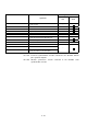
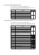
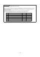
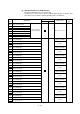

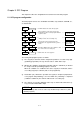

Table Of Contents
- Coverpage
- Safety Instructions
- Revision History
- Contents
- Introduction
- 1 Outline
- 2 Explanation of Functions
- 3 Q-PLC Multi-CPU
- 4 Q Motion CPU
- 5 SFC Program
- 6 SV22 Servo Programs
- 6.1 Servo program
- 6.1.1 Servo program configuration
- 6.1.2 List of servo commands
- 6.1.3 Linear control
- 6.1.4 Circular interpolation control using auxiliary point designation
- 6.1.5 Circular interpolation control using radius designation
- 6.1.6 Circular interpolation control using center point designation
- 6.1.7 Fixed-dimension feed control
- 6.1.8 Speed control
- 6.1.9 Speed/position changeover control
- 6.1.10 Speed changeover control
- 6.1.11 Constant-speed control
- 6.1.12 Repeated control (for speed changeover control and uniform speed control)
- 6.1.13 Simultaneous start
- 6.1.14 Zero point return
- 6.1.15 Position follow-up control
- 6.1.16 High-speed oscillation control
- 6.1.17 Helical interpolation control with auxiliary point designated
- 6.1.18 Helical interpolation control with radius designated
- 6.1.19 Helical interpolation control with center point designated
- 6.1.20 Current value change
- 6.1 Servo program
- 7 Operation Control Program
- 8 Windows Personal Computer Operations
- 9 Basic Practice Using the SV22 Real Mode
- 10 Applied Practice with SV22 Real Mode
- 10.1 Details of practice
- 10.2 Q172CPU practice machine system configuration
- 10.3 Practice SFC programs
- 10.4 Writing to the motion CPU
- 10.5 Program for operation
- 10.5.1 JOG operation
- 10.5.2 Main routine SFC program (real mode operation)
- 10.5.3 Execution of servo program (motion control step)
- 10.5.4 Stopping
- 10.5.5 Error reset
- 10.5.6 Current value change
- 10.5.7 Speed change (CHGV)
- 10.5.8 Reading actual current value
- 10.5.9 Continuous positioning
- 10.5.10 M code function
- 10.5.11 Indirect setting of servo program address
- 10.6 Operating the practice machine
- 11 Practicing with the SV22 Virtual Mode
- 11.1 Mechanism program
- 11.2 Details of practice
- 11.3 Starting up SW3RN-CAMP and creating the cam
- 11.4 SFC program for virtual mode
- 11.5 Editing the mechanism
- 11.6 Writing to the motion CPU
- 11.7 Reading of sequence program from Q-PLC CPU
- 11.8 SFC program for practice
- 11.9 Practice machine operations
- 11.10 Exercise (Roller setting)
- Appendix
5 - 1
Chapter 5 SFC Program
This chapter describes the configuration and each element of the SFC program.
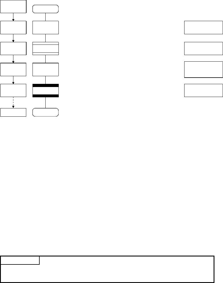
5.1 SFC program configuration
The SFC program consists of a combination of START, step, transition, and END, etc.,
as shown below.
Operation
start
F0
G0
K0
G1
END
• • • • •
• • • • •
• • • • •
• • • • •
• • • • •
• • • • •
• • • • •
• • • • •
• • • • •
• • • • •
Positioning
preparation
Positioning pre-
paration com-
pletion check
Program name
START: Indicates the start of the program.
Step (operation control step): Executes the
designated operation control program while the
system is active.
Transition (shift): Indicates the conditions for
shifting control to the succeeding step.
Step (motion control step): Executes the
designated servo program while the system is
active.
Transition (WAIT): Shows the condition to shift
the control to the succeeding step.
END: Shows the end of program.
Execution of
positioning
Positioning
completion
check
Operation end
SET Y0=X0+X10
D100=W0+W100
Y0+M100
ABS-1
Axis 1, D100
Speed 10000
!X0
The running SFC program operates as follows.
(1) The step (F0) is activated, and the designated operation is executed at step (F0)
(positioning preparation). The step in active state is called "Active step".
(2) Whether the conditions designated by transition (G0) are established (or whether
it is ready to start the positioning program) is checked.
When the conditions are established, the active step (F0) is inactivated, and the
succeeding step (K0) is activated (start of servo program K0).
(3) At transition (G1), whether the operation at step (K0) is completed (completion of
servo program K0 positioning) is checked. When the positioning is completed
(conditions established), the control is shifted to the succeeding step.
(4) The control is executed by shifting the active step as shown in the above items (1)
to (3), and ended when END is input.
POINT
The number of steps that can be an active step simultaneously is 256 or less (total
in all SFC programs).