
Specifications

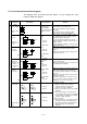
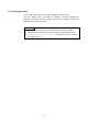
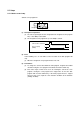
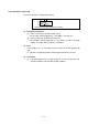
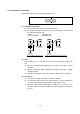
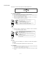
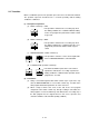
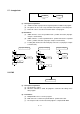
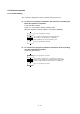
Table Of Contents
- Coverpage
- Safety Instructions
- Revision History
- Contents
- Introduction
- 1 Outline
- 2 Explanation of Functions
- 3 Q-PLC Multi-CPU
- 4 Q Motion CPU
- 5 SFC Program
- 6 SV22 Servo Programs
- 6.1 Servo program
- 6.1.1 Servo program configuration
- 6.1.2 List of servo commands
- 6.1.3 Linear control
- 6.1.4 Circular interpolation control using auxiliary point designation
- 6.1.5 Circular interpolation control using radius designation
- 6.1.6 Circular interpolation control using center point designation
- 6.1.7 Fixed-dimension feed control
- 6.1.8 Speed control
- 6.1.9 Speed/position changeover control
- 6.1.10 Speed changeover control
- 6.1.11 Constant-speed control
- 6.1.12 Repeated control (for speed changeover control and uniform speed control)
- 6.1.13 Simultaneous start
- 6.1.14 Zero point return
- 6.1.15 Position follow-up control
- 6.1.16 High-speed oscillation control
- 6.1.17 Helical interpolation control with auxiliary point designated
- 6.1.18 Helical interpolation control with radius designated
- 6.1.19 Helical interpolation control with center point designated
- 6.1.20 Current value change
- 6.1 Servo program
- 7 Operation Control Program
- 8 Windows Personal Computer Operations
- 9 Basic Practice Using the SV22 Real Mode
- 10 Applied Practice with SV22 Real Mode
- 10.1 Details of practice
- 10.2 Q172CPU practice machine system configuration
- 10.3 Practice SFC programs
- 10.4 Writing to the motion CPU
- 10.5 Program for operation
- 10.5.1 JOG operation
- 10.5.2 Main routine SFC program (real mode operation)
- 10.5.3 Execution of servo program (motion control step)
- 10.5.4 Stopping
- 10.5.5 Error reset
- 10.5.6 Current value change
- 10.5.7 Speed change (CHGV)
- 10.5.8 Reading actual current value
- 10.5.9 Continuous positioning
- 10.5.10 M code function
- 10.5.11 Indirect setting of servo program address
- 10.6 Operating the practice machine
- 11 Practicing with the SV22 Virtual Mode
- 11.1 Mechanism program
- 11.2 Details of practice
- 11.3 Starting up SW3RN-CAMP and creating the cam
- 11.4 SFC program for virtual mode
- 11.5 Editing the mechanism
- 11.6 Writing to the motion CPU
- 11.7 Reading of sequence program from Q-PLC CPU
- 11.8 SFC program for practice
- 11.9 Practice machine operations
- 11.10 Exercise (Roller setting)
- Appendix

5 - 3
Division Designation
Symbol
(code size: byte)
List expression
Function
SHIFT
(shifting to
advance
reading)
Gn
(8)
SFT Gn
• If the last step is a motion control step, the operation is
shifted to the succeeding step when the shifting conditions
Gn (G0 to G4095) are established without waiting for the
motion to end.
• If the last step is an operation control step, the operation is
shifted to the succeeding step when the shifting conditions
are established after execution of operation.
• If the last step is a subroutine call/start step, the operation is
shifted to the succeeding step when the shifting conditions
are established without waiting for the subroutine to end.
WAIT
Gn
(8)
WAIT Gn
• If the last step is a motion control step, the operation is
shifted to the succeeding step when the shifting conditions
Gn (G0 to G4095) are established without waiting for the
motion to end.
• If the last step is an operation control step, the operation is
shifted to the succeeding step when the shifting conditions
are established after execution of operation. (Same
operation as SHIFT)
• If the last step is a subroutine call/start step, the operation is
shifted to the succeeding step when the shifting conditions
are established without waiting for the subroutine to end.
WAITON
ON bit device
Kn
(14)
WAITON
bit device
• Prepares to start the succeeding motion control step, and
outputs the control command as soon as the designated
bit device is turned ON.
• Be sure to set it together with motion control step in pairs
(1:1).
WAITOFF
OFF bit device
Kn
(14)
WAITOFF
bit device
• Prepares to start the succeeding motion control step, and
outputs the control command as soon as the designated
bit device is turned OFF.
• Be sure to set it together with motion control step in pairs
(1:1).
SHIFT Y/N
Gn
N
(When the
conditions fail to
be established)
(When the
conditions are
established)
Y
IFBm
IFT1
SFT Gn
:
JMP IFEm
IFT2
SFT Gn+?
:
JMP IFEm
IFEm
• If the last step is a motion control step, the operation is
shifted to the succeeding step when the shifting conditions
Gn (G0 to G4095) are established without waiting for the
motion to end. If the conditions are not established, shifts
to the step connected to the right.
• If the last step is an operation control step, the operation is
shifted to the lower step when the shifting conditions are
established after execution of operation. If the conditions
are not established, shifts to the step connected to the
right.
• If the last step is a subroutine call/start step, the operation is
shifted to the lower step when the shifting conditions are
established before the operation of subroutine is completed.
If the conditions are not established, shifts to the step
connected to the right.
Transition
WAIT Y/N
Gn
N
(When the
conditions fail to
be established)
(When the
conditions are
established)
Y
IFBm
IFT1
WAIT Gn
:
JMP IFEm
IFT2
WAIT Gn+?
:
JMP IFEm
IFEm
• If the last step is a motion control step, the operation is
shifted to the lower step when the shifting conditions Gn
(G0 to G4095) are established after the operation of
motion is completed. If the conditions are not established,
shifts to the step connected to the right.
• If the last step is an operation control step, the operation is
shifted to the lower step when the shifting conditions are
established after execution of operation. If the conditions
are not established, shifts to the step connected to the
right. (Same operation as SHIFT)
• If the last step is a subroutine call/start step, the operation
is shifted to the lower step when the shifting conditions are
established after the operation of subroutine is completed.
If the conditions are not established, shifts to the step
connected to the right.
Jump JUMP
Pn
(14)
JMP Pn
• Jumps to the designated pointer Pn (P0 to P16383) within
the local program.
Pointer POINTER
Pn
(8)
Pn
• Indicates the jump destination pointer (label).
• The step, transition, branch point and connection point
can be set.
• P0 to P16383 can be set in one program. The program
No. may be overlapped with another program No.