
Specifications

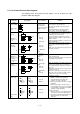
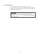
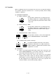
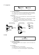
Table Of Contents
- Coverpage
- Safety Instructions
- Revision History
- Contents
- Introduction
- 1 Outline
- 2 Explanation of Functions
- 3 Q-PLC Multi-CPU
- 4 Q Motion CPU
- 5 SFC Program
- 6 SV22 Servo Programs
- 6.1 Servo program
- 6.1.1 Servo program configuration
- 6.1.2 List of servo commands
- 6.1.3 Linear control
- 6.1.4 Circular interpolation control using auxiliary point designation
- 6.1.5 Circular interpolation control using radius designation
- 6.1.6 Circular interpolation control using center point designation
- 6.1.7 Fixed-dimension feed control
- 6.1.8 Speed control
- 6.1.9 Speed/position changeover control
- 6.1.10 Speed changeover control
- 6.1.11 Constant-speed control
- 6.1.12 Repeated control (for speed changeover control and uniform speed control)
- 6.1.13 Simultaneous start
- 6.1.14 Zero point return
- 6.1.15 Position follow-up control
- 6.1.16 High-speed oscillation control
- 6.1.17 Helical interpolation control with auxiliary point designated
- 6.1.18 Helical interpolation control with radius designated
- 6.1.19 Helical interpolation control with center point designated
- 6.1.20 Current value change
- 6.1 Servo program
- 7 Operation Control Program
- 8 Windows Personal Computer Operations
- 9 Basic Practice Using the SV22 Real Mode
- 10 Applied Practice with SV22 Real Mode
- 10.1 Details of practice
- 10.2 Q172CPU practice machine system configuration
- 10.3 Practice SFC programs
- 10.4 Writing to the motion CPU
- 10.5 Program for operation
- 10.5.1 JOG operation
- 10.5.2 Main routine SFC program (real mode operation)
- 10.5.3 Execution of servo program (motion control step)
- 10.5.4 Stopping
- 10.5.5 Error reset
- 10.5.6 Current value change
- 10.5.7 Speed change (CHGV)
- 10.5.8 Reading actual current value
- 10.5.9 Continuous positioning
- 10.5.10 M code function
- 10.5.11 Indirect setting of servo program address
- 10.6 Operating the practice machine
- 11 Practicing with the SV22 Virtual Mode
- 11.1 Mechanism program
- 11.2 Details of practice
- 11.3 Starting up SW3RN-CAMP and creating the cam
- 11.4 SFC program for virtual mode
- 11.5 Editing the mechanism
- 11.6 Writing to the motion CPU
- 11.7 Reading of sequence program from Q-PLC CPU
- 11.8 SFC program for practice
- 11.9 Practice machine operations
- 11.10 Exercise (Roller setting)
- Appendix

5 - 4
5.3 List of branch/connection diagrams
The following shows the branch/connection patterns used to designate the steps/
transitions within SFC diagram.
Designation
(code size:
byte)
SFC symbol List expression Function
Series shifting
(Each symbol
size)
Refer to the list
corresponding to
symbol shown in SFC
diagram of section
5.2.
• Sequentially executes steps and transitions
connected in a series from the top.
• The steps and transitions may be arranged
alternately.
• When the transition is omitted, the shifting
processing is executed unconditionally.
Selective
branch
(Number of
branches + 2
× 10)
IFBm
IFT1
IFT2
• Executes the route for which shifting conditions
are established first after execution of step or
transition just before the branch.
• The head of branch destination for selective
branch is limited to transitions, and must be all
SHIFT or WAIT.
(When the SHIFT and WAIT co-exist, it becomes
the parallel branch.)
Selective
connection
(8)
IFEm
CALL Kn
IFBm
IFT1
SFT Gn
CALL Fn
:
JMP IFEm
IFT2
SFT Gn'
CALL Fn'
:
( JMP IFEm )
IFEm
CALL Fn''
• Shifts to the connection point after execution of
processing for route branched by selective
branch.
• Either step or transition may be used just before
and after connection.
Parallel branch
(Number of
branches × 22
+ Number of
connections ×
2 + 12)
PABm
PAT1 PAT2
• Executes the multiple routes (steps) connected in
series simultaneously.
• Either step or transition may be used at the head
of parallel branch destination.
Parallel
connection
(8)
PAEm
SFT Gn
PABm
PAT1
CALL Fn
SFT Gn'
:
JMP PAEm
PAT2
CALL Fn'
SFT Gn''
:
( JMP PAEm )
PAEm
CALL Fn''
:
• Waits for completion of execution at each route
branched by parallel branch, and shifts to the
succeeding step after completion of execution for
all routes.
Either step or transition may be used just before
and after connection.
• When the step just before connection is an FS
step, the scan is executed even if the system is
waiting. The scan is not executed after
completion of waiting.
<Normal jump> <Jump (connection)>
CALL Fn
JMP Pn
Basic type
Jump (shift)
(Each symbol
size)
CALL Fn'
Pn
CALL Kn
(1) Normal jump
• Shifts the execution to the pointer Pn
designated within local program after
execution of last step or transition.
• Either step or transition may be used at jump
destination.
• Even when the jump is executed from FS
step to transition, the scan is executed while it
is under waiting for establishment of shifting
conditions for jump destination.
(2) Jump (connection)
• "Jump (connection)" occurs when the jump is
executed to the other route within parallel
branch after completion of parallel branch, in
which the waiting is executed at jump
destination.