
Specifications
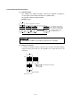
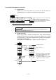
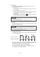
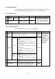
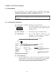
Table Of Contents
- Coverpage
- Safety Instructions
- Revision History
- Contents
- Introduction
- 1 Outline
- 2 Explanation of Functions
- 3 Q-PLC Multi-CPU
- 4 Q Motion CPU
- 5 SFC Program
- 6 SV22 Servo Programs
- 6.1 Servo program
- 6.1.1 Servo program configuration
- 6.1.2 List of servo commands
- 6.1.3 Linear control
- 6.1.4 Circular interpolation control using auxiliary point designation
- 6.1.5 Circular interpolation control using radius designation
- 6.1.6 Circular interpolation control using center point designation
- 6.1.7 Fixed-dimension feed control
- 6.1.8 Speed control
- 6.1.9 Speed/position changeover control
- 6.1.10 Speed changeover control
- 6.1.11 Constant-speed control
- 6.1.12 Repeated control (for speed changeover control and uniform speed control)
- 6.1.13 Simultaneous start
- 6.1.14 Zero point return
- 6.1.15 Position follow-up control
- 6.1.16 High-speed oscillation control
- 6.1.17 Helical interpolation control with auxiliary point designated
- 6.1.18 Helical interpolation control with radius designated
- 6.1.19 Helical interpolation control with center point designated
- 6.1.20 Current value change
- 6.1 Servo program
- 7 Operation Control Program
- 8 Windows Personal Computer Operations
- 9 Basic Practice Using the SV22 Real Mode
- 10 Applied Practice with SV22 Real Mode
- 10.1 Details of practice
- 10.2 Q172CPU practice machine system configuration
- 10.3 Practice SFC programs
- 10.4 Writing to the motion CPU
- 10.5 Program for operation
- 10.5.1 JOG operation
- 10.5.2 Main routine SFC program (real mode operation)
- 10.5.3 Execution of servo program (motion control step)
- 10.5.4 Stopping
- 10.5.5 Error reset
- 10.5.6 Current value change
- 10.5.7 Speed change (CHGV)
- 10.5.8 Reading actual current value
- 10.5.9 Continuous positioning
- 10.5.10 M code function
- 10.5.11 Indirect setting of servo program address
- 10.6 Operating the practice machine
- 11 Practicing with the SV22 Virtual Mode
- 11.1 Mechanism program
- 11.2 Details of practice
- 11.3 Starting up SW3RN-CAMP and creating the cam
- 11.4 SFC program for virtual mode
- 11.5 Editing the mechanism
- 11.6 Writing to the motion CPU
- 11.7 Reading of sequence program from Q-PLC CPU
- 11.8 SFC program for practice
- 11.9 Practice machine operations
- 11.10 Exercise (Roller setting)
- Appendix
5 - 14
5.9.3 Parallel branch/parallel connection
(1) Parallel branch
Multiple steps, connected in parallel, are executed at the same time. Either step
or transition may be used at the head of parallel branch destination.
G1
K2
WAIT G0
G2
G3
G255
K3 F1 F10
G0
Maximum number of selective branches = 255
The steps from K2 to F10, connected in parallel,
are executed when the conditions set for
transition G0 are established after operation of
last step, and executed thereafter for each route
up to the parallel connection point.
POINT
"SHIFT" or "WAIT" can be set for the transition just before parallel branch, but
"WAITON" and "WAITOFF" cannot be set.
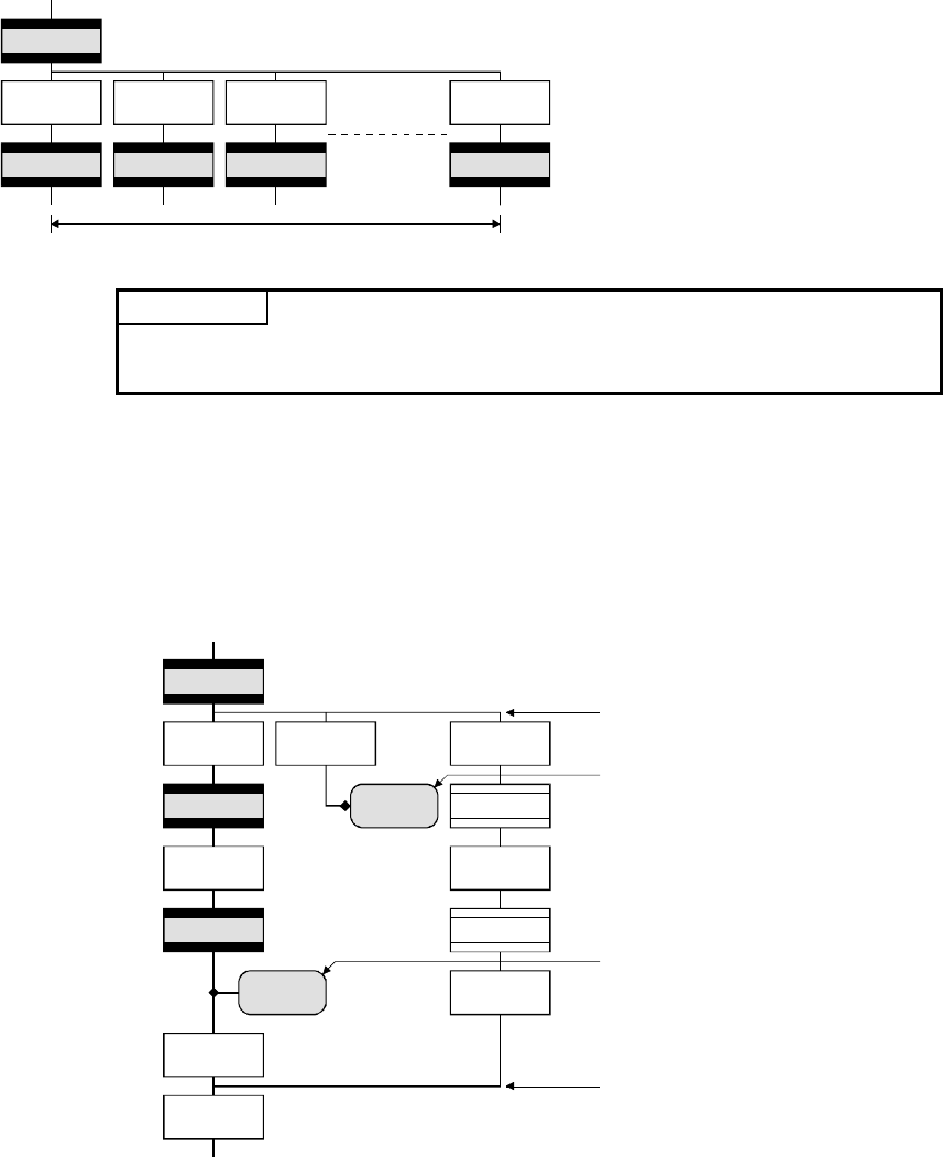
(2) Parallel connection
Always connect with a parallel connection when using parallel branching.
Jumping to another branch route can be set between the parallel branch – parallel
connection. In this case, the jump destination will be a parallel connection point in
the middle (connection jump).
A jump that exits the parallel branch – parallel connection cannot be set.
F10
G1
K2
ON M100
K4
ON M100
K3
PAB1
PAE1
K100
K5
G12
G11
F1
F12
Parallel branch point
Jump (connection)
Waits until the conditions set by transition
G3 are established and the start of servo
program K4 is completed after the servo
program K3 is stopped.
The operation is shifted to the succeeding
(next) step after completion of waiting.
Parallel connection point